Element Extraction
The Element Extraction module is used to extract element in the scene. The module provides intersection drawing line, Semi-automatic building contour vectorization and road ridge vectorization. The vectorized objects of this module are buildings or roads. When starting any function of this module, if there is no layer currently, the software will automatically add a layer. will be stored on the layer.
Vectorized buildings with Draw by Intersection
Start the function of vectorized buildings with Draw by Intersection
Click the left mouse button to select two points on one side of the building in tum.
Click the left mouse button to select two points on the other side of the building in turn.
The two selected edges will automatically extend to meet the intersection point.
(Optional) Right-dick the mouse to pop up a right-click menu, and select Close Polyline, Back Point, or End Current.
(Optional) Click the back button on the toolbar to back the selected vertex.
(Optional) Click the tool bar close button to automatically close the current polyline and end the drawing of the current intersection drawing method.
Extract Building Footprint

Start the function of semi-automatic building outline vectorization
 Click extract building footprint from mesh button.
A parameter dialog box will pop up:
Click extract building footprint from mesh button.
A parameter dialog box will pop up:
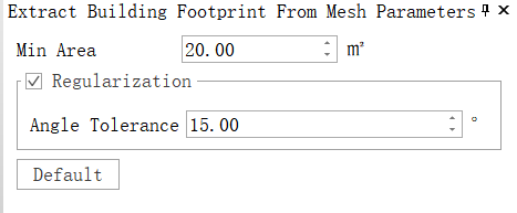
Min Area: The minimum area to extract from a region. Boundaries smaller than this size will be discarded.
Regularization: Whether to perform regularization or not. After enabling this function, simplify and regularize extracted boundaries accordingly.
Angle Tolerance: Effective after regularization is enabled; sets an angle threshold for regularization which is set between 15° - 30° degrees by default. Larger values result in fewer sharp corners on edges.
Road Ridge Vectorization
Enable semi-automatic Road Ridge vectorization function
- Click the left mouse button for the first time to determine the location of the search box. It is appropriate to select the location close to the middle of the curb stone facade.
- When an intersecting ridge appears, click the mouse to extract the ridge. Click the left mouse button for the second time to determine the search direction, specify the forward direction of the curb, and start execution wait.
- Automatically extracts the upper and lower edges of the kerb and adds them to the current layer.
- (Optional) Click the back button on the toolbar to back out the last extracted ridge.
- (Optional) Click the redo button on the toolbar to re-add the retreat of the last ridge extraction.
Parameters Settings
- Length(m): The length of search box, with default of 0.5 m. The larger the value, the faster the search speed, but too large a value will span two sections of roads that are not connected.
- Width(m): The width of search box, with default of 0.2 m. It can cover the kerb area, and should not be too large.
- Height(m): The height of search box. Set it according to the height of the road ridge to be extracted, slightly larger than the road ridge, and adjust it through the height indicator line.
- Angle threshold (degree): the degree of curvature on the strike of the kerb. For the curve of the arc road, the default value is 30°.