Entity Vectorization
Entity vectorization, including vectorization of point, line and polygon entities, also provides specific editing functions for polylines and polygons respectively.
Note: Point layers can only add point objects, not line, circle, polyline and polygon objects. Line layers cannot add point entities, only line, polyline, and polygon objects.
Point

Draw the entity point by clicking the left mouse button. The operation steps are as follows.
- Click the left mouse button to select the point entity position.
- Repeat step 1 to draw the next point entity.
- Click the right mouse button to end drawing the point entity.
Two-point Polyline

Draw a line segment entity by clicking the left mouse button to draw the start point. The operation steps are as follows.
- Click the left mouse button to select the starting point of the line segment entity, or right-click to end the drawing of the line segment entity.
- Click the left mouse button to select the end point of the line segment entity, or right-click to go back to Step 1.
- Click the right mouse button to end drawing the line segment entity.
Polyline
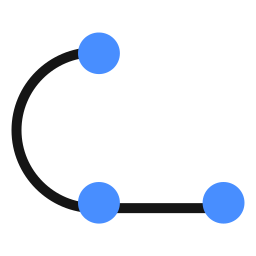
Draw polylines interactively with the mouse.
- Click the left mouse button to select a point, or click the right mouse button to exit drawing a polyline.
- Repeat step 1 to add points, or click the right mouse button to end the current polyline drawing. To close the polyline, click the close button, and repeat step 1 to start a new polyline drawing.
- Click the right mouse button to exit drawing the polyline.
B-Spline Curve
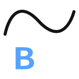
Draw B-spline curves interactively with the mouse.
- Click the left mouse button to select a point, or click the right mouse button to quit drawing the B-spline curve.
- Repeat step 1 to add points, or right-click to end the drawing of the current B-spline curve. To close the curve, click the close button, and repeat step 1 to start drawing a new B-spline curve.
- Click the right mouse button to exit drawing the B-spline curve.
Bezier Curve

Draw a Bezier curve interactively with the mouse.
- Click the left mouse button to select a point, or click the right mouse button to quit drawing the Bezier curve.
- Repeat step 1 to add points, or click the right mouse button to end the drawing of the current Bezier curve. To close the curve, click the close button, and repeat step 1 to start drawing a new Bezier curve.
- Click the right mouse button to exit drawing Bezier curves.
Circle

Draw a circle interactively with the mouse.
- Click the left mouse button to select the center of the circle, or click the right mouse button to exit the circle drawing.
- Double-click the left mouse button to select a point on the circle, or right-click to go back to Step 1.
- Click the right mouse button to exit drawing the circle.
Two-Point Circle
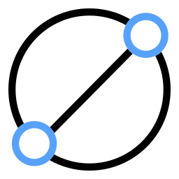
Draw a circle interactively with the mouse.
- Click the left mouse button to select an endpoint on the diameter of the circle, or click the right mouse button to exit the two-point circle drawing.
- Double-click the left mouse button to select another endpoint on the circle diameter, or right-click to go back to Step 1.
- Click the right mouse button to exit the two-point circle drawing.
Three-Point Circle
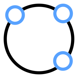
Draw a circle interactively with the mouse.
- Click the left mouse button to select a point on the circle, or click the right mouse button to exit the three-point circle drawing.
- Click the left mouse button to select the second point on the circle, or right-click to go back to Step 1.
- Double-click the left mouse button to select the third point on the circle, or right-click to go back to Step 2.
- Click the right mouse button to exit the three-point circle drawing.
Three-Point Arc

Draw an arc interactively with the mouse.
- Click the left mouse button to select the first point on the arc, or click the right mouse button to exit the three-point arc drawing.
- Click the left mouse button to select the second point on the arc, or click the left mouse button to go back to Step 1.
- Double-click the left mouse button to select the third point on the arc, or click to go back to Step 2.
- Click the right mouse button to exit the three-point arc drawing.
Three-Point Rectangle
Draw a rectangle interactively with the mouse.
- Click the left mouse button to select a point, or click the right mouse button to exit drawing the rectangle.
- Repeat step 1 to add points. After clicking three points, the current drawing ends. Repeat step 1 to start a new rectangle drawing.
Draw Polygon
Draw a polygon with editing functions for adding and deleting nodes.
- Click the left mouse button to select a point, or click the right mouse button to exit drawing polygons.
- Repeat step 1 to add points, or click the right mouse button to end the current polygon drawing. Repeat step 1 to start a new polygon drawing.
- Click the right mouse button to exit drawing polygons.
Text Annotation

Add text annotation.
- Click the text annotation function button to open the text settings panel and configure the parameters.
- Left-click with the mouse to place the text annotation, or right-click to exit drawing the text annotation.
Parameter Settings
- Text: Sets the content of the text annotation to be added.
- Rotation (angle): The rotation angle for the text, counterclockwise direction.
- Height: The height of the text.
Add Node
Interactively edit polylines or polygons by adding nodes with the mouse.
- Click the left mouse button to select the polyline or polygon entity to be edited, or click the right mouse button to exit editing.
- Left-click on a polyline or polygon entity to add a node at that location, or right-click to end the current edit. Repeat the steps to start a new edit.
- Click the right mouse button to exit adding nodes.
Append Node
Interactively edit polylines, B-spline curves or Bezier curves by appending nodes at the start or end.
- Click the left mouse button to select the polyline entity to be edited, or click the right mouse button to exit editing.
- Click the left mouse button to select a point. The insertion position is determined by distance: if closer to the start, the point is added before the starting point; otherwise, it is added after the ending point. Right-click to end the current polyline editing. Repeat the steps to begin a new polyline edit.
- In the attribute panel on the right, select the type of line segment to be appended (Polyline, B-Spline Curve, Bezier Curve). The default is Polyline. Left-click to switch between the three types.
- Click the right mouse button to exit appending nodes.
Delete Node

Interactively edit polygons by deleting nodes with the mouse.
- Click the left mouse button to select the polyline or polygon entity to be edited, or click the right mouse button to exit editing.
- Click the left mouse button on a polygon entity node to delete that node, or right-click to end the current edit. Repeat the steps to start a new edit.
- Click the right mouse button to exit deleting nodes.
Break at Line
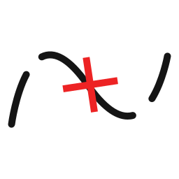
Interactively edit polylines by breaking at lines with the mouse.
- Click the left mouse button to select the polyline, B-spline curve or Bezier curve to be edited, or click the right mouse button to exit editing.
- Click the left mouse button to select the first intersection point on the polyline, or right-click to end the current edit. Repeat step 1 to start a new edit.
- Click the left mouse button to select the second intersection point on the polyline to complete the break, or right-click to go back and reselect the first intersection point.
- Click the right mouse button to exit breaking at line.
Break at Point
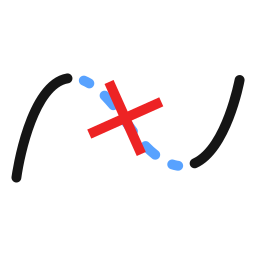
Interactively edit polylines by breaking at a point with the mouse.
- Click the left mouse button to select the polyline, B-spline curve or Bezier curve to be edited, or click the right mouse button to exit editing.
- Click the left mouse button to select an intersection point on the polyline, or right-click to end the current edit. Repeat step 1 to start a new edit.
- Click the right mouse button to exit breaking at point.
Merge
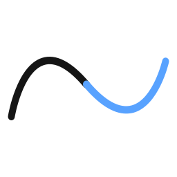
Interactively edit polylines by merging with the mouse.
- Click the left mouse button to continuously select multiple non-closed vector lines (polyline, B-spline curve or Bezier curve), then click the merge function to merge the selected vector lines.
- After clicking the merge function, click the left mouse button to continuously select the vector lines to be merged, then right-click to merge the selected vector lines.
- Click the left mouse button to select a vector line, then right-click to prepare selecting another vector line, then left-click to select the other vector line to complete the merge.
- Click the right mouse button to exit merging.
Join Polylines
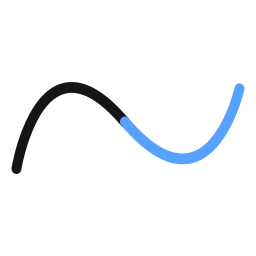
Interactively edit polylines by joining with the mouse.
- Click the left mouse button to select the start point or end point of the first vector line to be joined, or right-click to exit.
- Click the left mouse button to select the start point or end point of the second vector line to complete the join with the first vector line.
Intersect Polylines
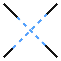
Interactively intersect multiple lines with the mouse.
- Click the left mouse button to select the first vector line for the intersection operation, or click the right mouse button to exit editing.
- Click the left mouse button to select the second vector line for the intersection operation, or right-click to go back to step 1.
- Select the desired intersection point to complete the intersection operation.
Trim
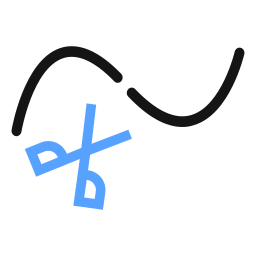
Interactively edit and trim polylines with the mouse.
- Click the left mouse button to select a polyline, rectangle or closed polyline as the reference line, or click the right mouse button to exit editing.
- After selecting a reference line, left-click to continue selecting reference lines, or right-click to prepare for selecting vector lines to trim.
- After entering the state of selecting vector lines to trim, click the left mouse button to select the vector line to trim. The selected vector line will be deleted based on its intersection with the reference line.
- Right-click to go back to reselect a reference line, and right-click again to exit trimming.
Note: The intersection point used for trimming judgment is on the XY plane and is independent of the vector elevation.
Reshape
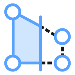
Reshape a feature by constructing a sketch line or area on the selected feature. The feature takes the shape of the sketch from the first intersection to the last intersection between the sketch and the feature.
- Click the left mouse button to select the polyline or polygon entity to be edited, or click the right mouse button to exit editing.
- Pick points in the scene.
- In the attribute panel on the right, select the line segment type for reshaping (Polyline, B-Spline Curve, Bezier Curve). The default is Polyline. Left-click to switch between the three types.
- Double-click on the polyline or polygon boundary to end the current edit.
- The reshaping tool has two modes: automatic selection and manual selection. Automatic selection: For non-closed polylines, the newly drawn line segment directly replaces the portion between the first and last intersection points. For closed polylines, the newly created polygon with the larger area is kept by default. Manual selection: For closed polylines and polygons, both newly created polylines are retained; left-click to select the one to delete.
Cut Polygon
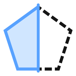
Split the selected polygon along the drawn line.
- Click the left mouse button to select the closed polyline or polygon entity to be edited, or click the right mouse button to exit editing.
- Pick points within the polyline or polygon area.
- Double-click on the polyline or polygon boundary to end the current edit.
Geometric Buffer
- Click to activate the Geometric Buffer function, then click the Apply button on the parameter interface. A buffer polygon will be generated for the selected vector in the currently active layer based on the buffer size.
Parameter Settings
- Buffer Size: The size of the buffer.
- End Cap Style: Options are Round, Square, and Flat.
- Join Style: Options are Round, Miter, and Bevel.
- Single-Sided Buffer: Left or right side buffer, applicable only to line segments. The generated buffer line is saved in the same layer as the original line segment.
Line Smoothing and Simplification

Smooth or simplify polylines.
- Click the Line Smoothing and Simplification button to open the parameter interface and configure the settings.
- Select the vector line object and click Execute.
Parameter Settings
- Enable Smoothing: Whether to apply smoothing.
- Smoothing Distance: Valid when smoothing is enabled. Specifies the average distance between adjacent points after smoothing.
- Enable Simplification: Whether to apply simplification.
- Simplification Distance: Specifies the maximum distance deviation for retaining points. A smaller distance retains more points and removes fewer points from the line.