Strip Adjustment
After the completion of Boresigt calibration, if the point cloud is still stratified, the error of the trajectory itself may be too large. The adjustment function can post-process the track and point cloud reduction errors.
Click Strip Alignment > Strip Adjustment button to pop up the Strip Adjustment interface. This function is mainly used to correct multiple trajectory fluctuation errors, and the point cloud data will be updated according to the corrected values.
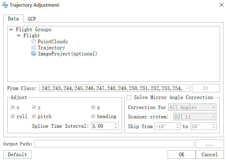
Single Sortie Strip Adjustment
In the strip adjustment interface, a sortie is taken as the unit, and each sortie requires three kinds of data, namely, tracking data, point cloud data and control point data (optional). Taking the single sortie strip adjustment as an example, there are two ways to create sortie units in the interface: by reading the LiGeo project file or creating manually.
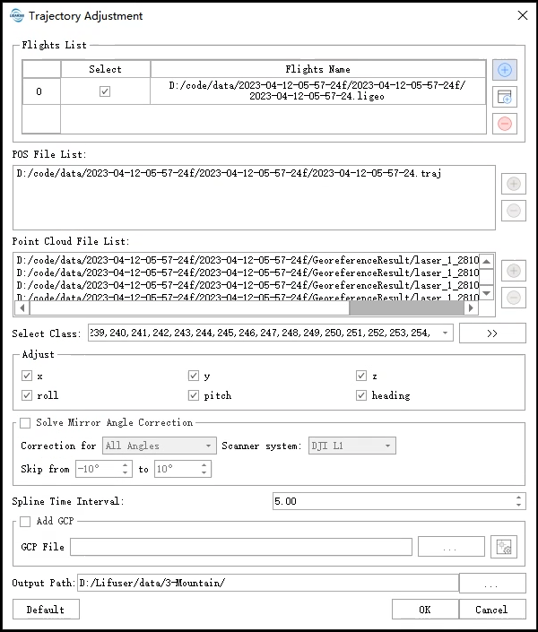
The first method: Click  button to pop up file dialog window, select the adjustment calculation LiGeo project files, software will automatically parse, then look for the project contained in trajectory data and point cloud data file path, and add it to the corresponding list, the process support relative path (that is, the project of mobile location), but please make sure that the tracking data is authentic; Otherwise, LiGeo project cannot be imported normally.
The second method: Click  button, fill in the name of the new sortie manually (it cannot be the same as other sorties), then select the sortie and add the corresponding tracking data and point cloud data file path.
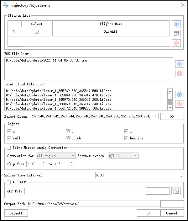
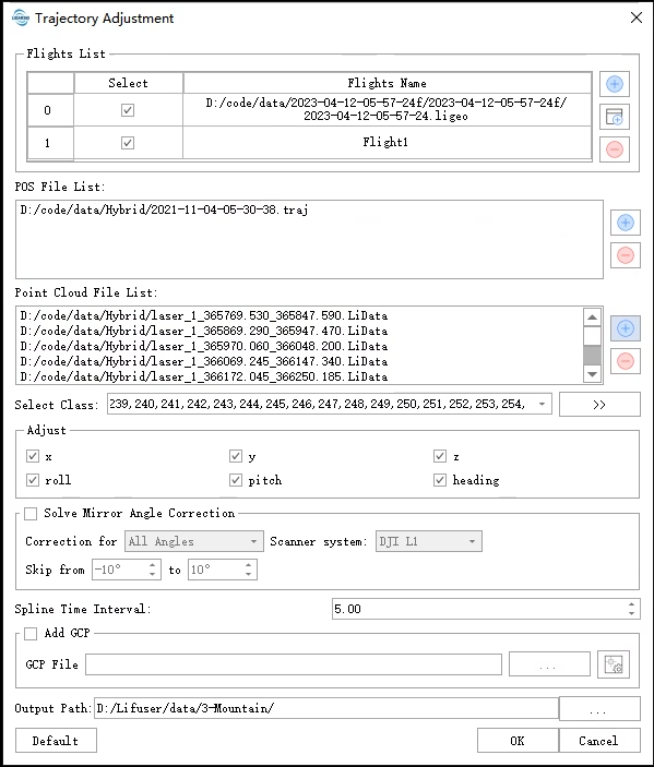
After the sortie is created and the corresponding tracking data and point cloud data are added, check the tracking component that needs to be corrected and set the time interval of tracking fluctuation. The user having control point data can select the control point option to add the corresponding control point file (.xml format). If it is the first time to add the file (txt format), users need to click the control point button to add corresponding matching points for each control point.
Add matching points manually: Click the control point button, and the control point dialog box will pop up. The top half of the box is the list of control points, and the bottom half is the list of matching points of each control point.
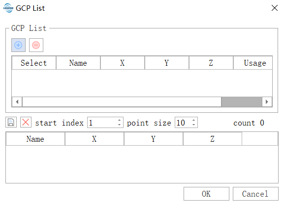
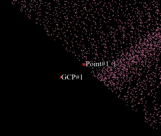
Each control point can correspond to multiple matching points, but the matching points in the same control point must come from different point cloud objects. For example, there are three matching points in control point 1, then the three matching points must be points in the three point cloud objects, and multiple matching points cannot be points in the same point cloud. The specific operation are as follows:
- Click button to pop up the file dialog window, select the control point file (txt format, file mainly includes X,Y,Z three fields information, see appendix).
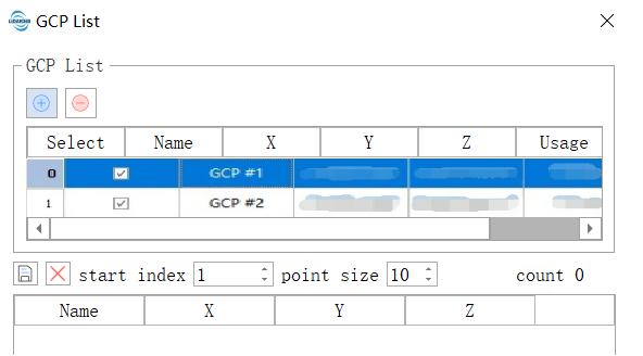
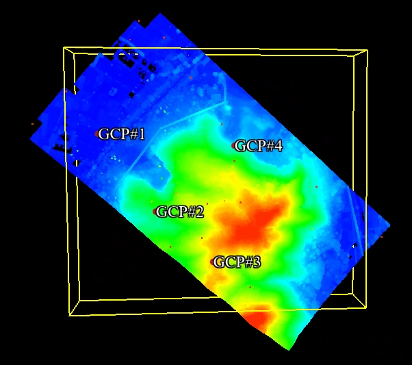
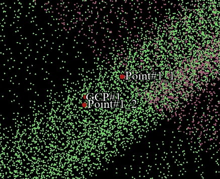
- Select one of the control point options, activate the mouse operation, double-click the option to jump to the control point, and then add corresponding matching points according to the point cloud, as shown in the figure.
- Click
 button, save the added results (xml format) and click OK in the end.
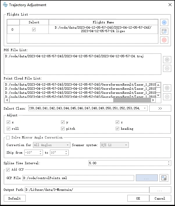
In addition, to make it easier for users to use the control point function, here is an overview of more operations:
Check Control Point If the control point file (xml file) has been added, you can check the position of each control point and its matching points in the control point file (xml file) by clicking the control point button.
Delete manually and add control points In the Control Point dialog box, select a control point option and right click the mouse to add or delete control points.
Set the type of Control Point The control points of the algorithm can be divided into two types: control points and check points. The former means that the control points will participate in the correction process of the trajectory adjustment. The latter means that the point only plays a verification role, mainly used to measure the absolute accuracy of adjustment results. In the dialog box, you can use the Usage to set the control point type.
After all the data is added, click "OK", the software will automatically execute the trajectory adjustment and correct the point cloud data.
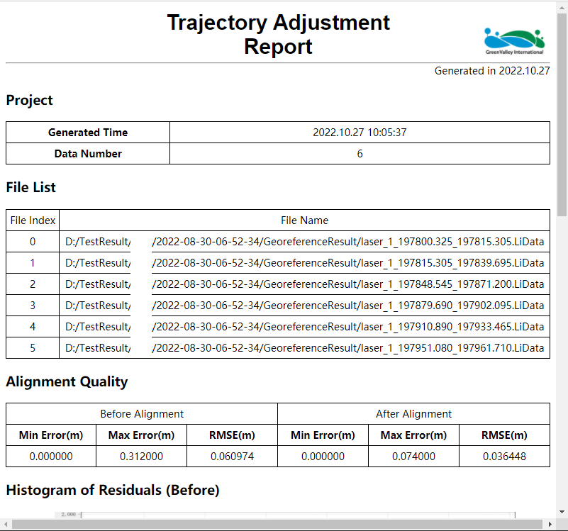
After the amendment is completed, the software will count the quality and generate HTML accuracy report. Click the report to open the generated HTML report.
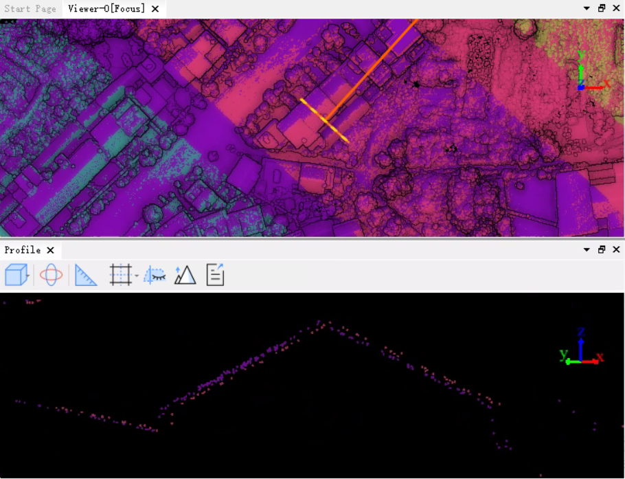
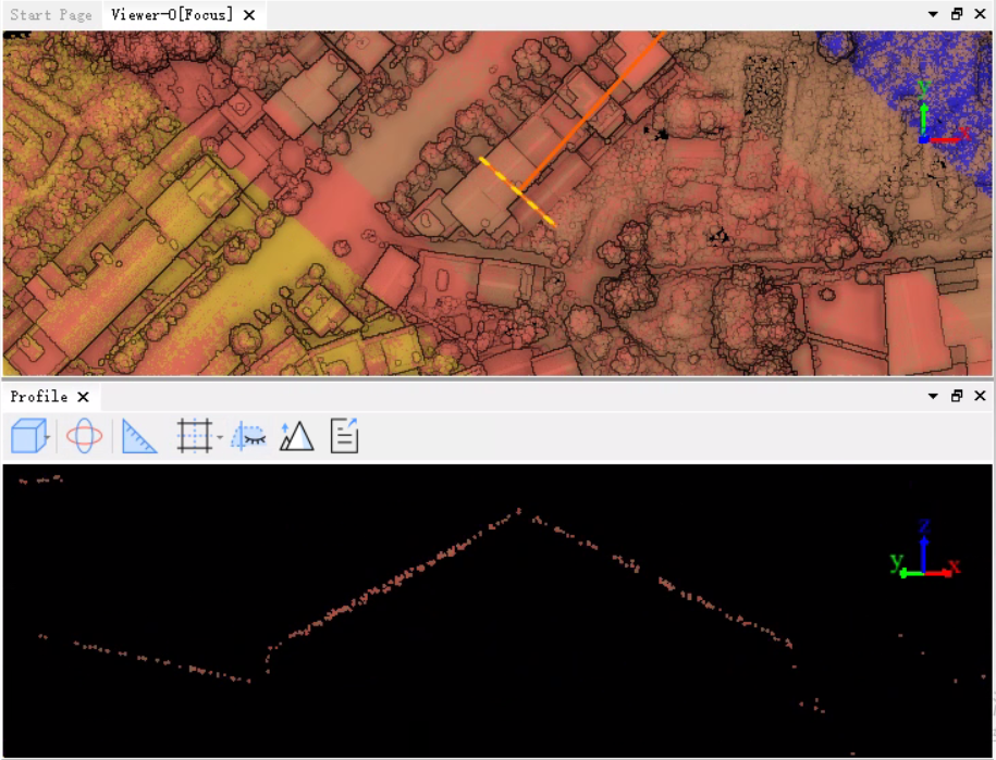
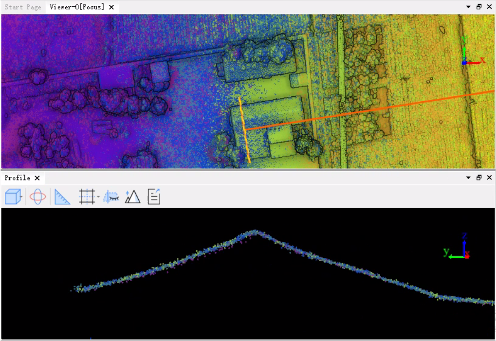
User can check the amendment results using the profile tool, as shown in the figure.
Parameters Settings
- Adjustment
- ΔX/ΔY/ΔZ: The positional component of the tracking amendment.
- ΔRoll/ΔPitch/ΔHeading: The angel component (Pitch ,Yaw,Roll) of the tracking amendment.
- Time interval (s): The tracking fluctuates based on the set time interval, and the shorter the interval, the higher the fluctuation frequency. If the local jitter of the tracking error is serious, a shorter interval can be set; otherwise, a longer interval can be used. The default values are valid for most data.
- Input Pos File: The flight tracking file corresponding to the point cloud involved in the amendment, and the supported POS data formats include .pos and .out.
Output path: The path where the result files are saved after the function is executed. The result files include: Amendment point clouds, amended flight tracking, and statistical quality HTML reports.
Note:In principle, the function need to enter the track line is to collect the cloud data file, the whole root routes but if there is no complete track line file, we can input multiple POS file after track line cutting, but we must ensure that the point cloud and track line match the GPS time, otherwise there will be a point cloud amendment error, tracking mismatch caused by leakage treatment.
Multiple sorties strip adjustment
Multiple sorties strip adjustment can be viewed as repeated operations of a single sortie strip adjustment. That is, add the sorties to be adjusted repeatedly to the interface, check the need to modify the path component, and set the interval between trajectory fluctuation nodes, click confirm and software will automatically execute multiple trajectory adjustment, and fixed point cloud data.
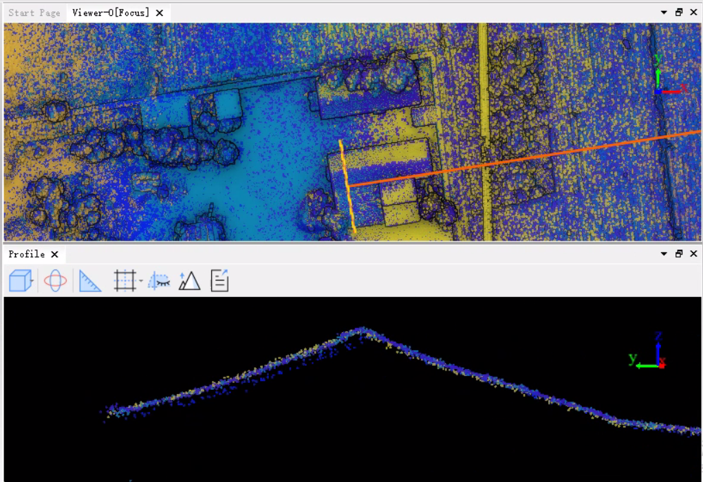
You can check the amendment results using the profile tool, as shown in the figure.
Note: The corresponding tracking data must be added for each sortie; otherwise, adjustment calculation cannot be performed.