Trajectory Adjustment
Functional Overview
If point clouds discrepancies are still obvious after Boresight, it may be caused by trajectory errors. With this tool, trajectories and related point clouds can be post-processed and refined.
The Trajectory Adjustment algorithm used in LiDAR360 is based on the literature reference (Glira et al., 2016). The basic algorithmic process is as follows:
- Extract feature points and their normal vectors in the overlapping regions of adjacent flight strips.
- Match the extracted feature points from adjacent flight strips to obtain matching point pairs.
- Construct a trajectory error correction model and calculate the distances along the normal vectors of the relevant point pairs.
- Use the least squares method to minimize the distance between matching point pairs and obtain an optimal solution for the trajectory correction.
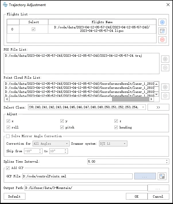
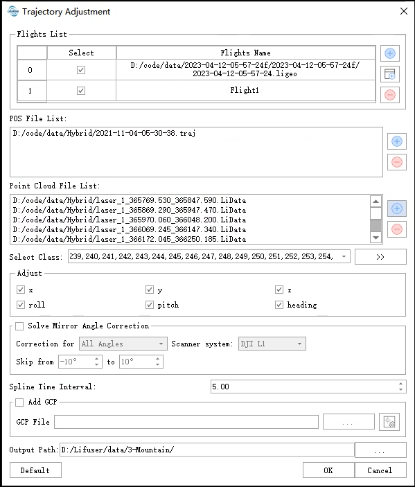
ClickPreprocessing>Trajectory Adjustmentbutton, the interface will pop up. This function estimates fluctuating errors of trajectory, then updates point clouds based on correction values..
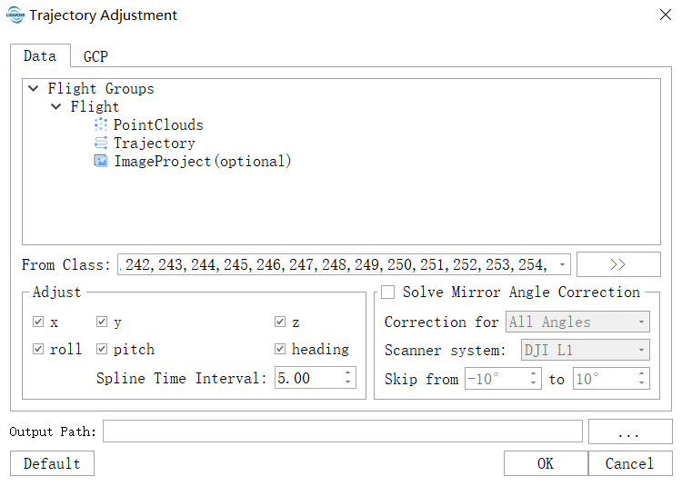
Single Flight Trajectory Adjustment
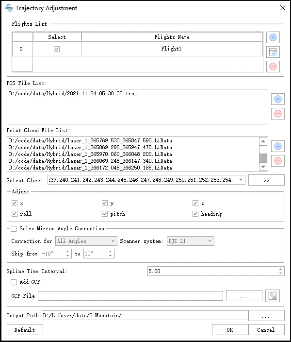
In the Trajectory Adjustment interface of LiDAR360, the unit measurement is based on flight. Each flight requires three types of data: trajectory data, point cloud data, and control point data (optional). Taking the single flight trajectory adjustment as an example, the interface supports you to manually create flight units. The specific process is as follows:
Click
button,manually create a new flight, fill in the name (which cannot be the same as an existing mission), select the flight, add the corresponding trajectory data and point cloud data. Once this is done, the flight is created.
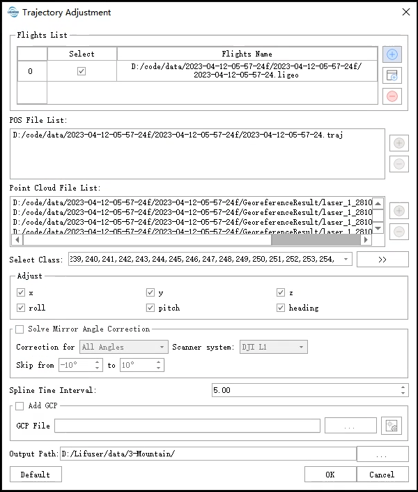
In addition, data can also be imported through LiGeo projects. Click button and select the LiGeo project file for which you want to perform adjustment calculations. The software will automatically parse and obtain trajectory and point cloud data, but please ensure that the data actually exists, otherwise the LiGeo project cannot be imported normally..
After creating the flight and adding corresponded trajectory and point cloud data, select the trajectory component that needs to be corrected and set the time interval of trajectory fluctuation nodes. If you have control point data, you can select the control point option to add the corresponding control point file (in XML format). If this is the first time adding the file (in TXT format), you need to click the control point button to add corresponding matching points for each control point manually.
To manually add point pairs, click the control point button to pop up the GCP List interface. The upper part displays the control point list, while the lower part displays the matching point list for each control point.
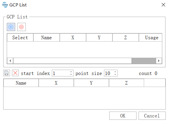
Each point pair can correspond to multiple matching points, but the matching points in a point pair must come from different point cloud objects. The specific operation process is described below:
1.Clickbutton,a file dialog box window pops up. Select the control point file (in txt format, containing X, Y, and Z field information. Please see the attachment for details).
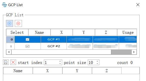
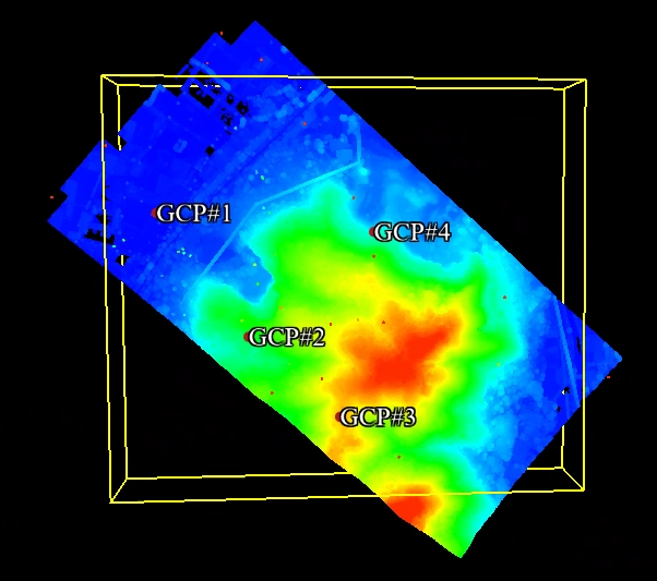
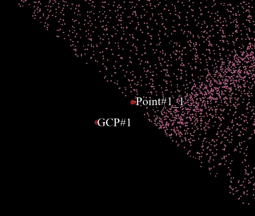
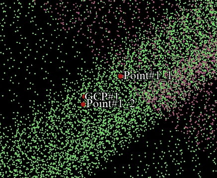
2.Select one of the control point options, activate mouse operation, and double-click the option to jump to the vicinity of the control point. Then, add corresponding matching points based on the point cloud situation, as shown in the figure.
- Click
 button,save the added results in XML format and click OK to finish..
In addition, in order to provide users with more convenient use of the control point function, this manual provides an overview of its additional operations:
1.View Control Points: If a control point file (XML file) has been added, the control point button can be clicked to view the position of each control point and its corresponding matched points in the control point file (XML file).
2.Manually delete and add control points. In the control point dialog, select a control point option and right-click the mouse to perform control point deletion or addition.
3.Setting Control Point Type. This algorithm mainly categorizes control points into two types: control points and check points. The former will participate in the strip adjustment correction process, while the latter only serves a verification purpose, mainly used to measure the absolute accuracy of the adjustment results. In the dialog box, the control point type can be set by using the Usage field.
After adding all the data, click "OK" and the software will automatically perform strip adjustment and correction of the point cloud data.
After the completion of the correction, LiDAR360 software will automatically perform quality assessment and generate an HTML accuracy report. The report will be saved in working directory/report. Click on report.html to open the generated accuracy report
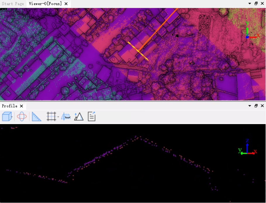
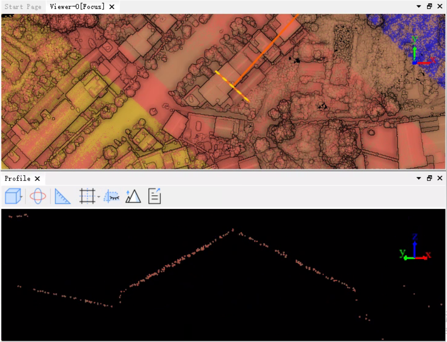
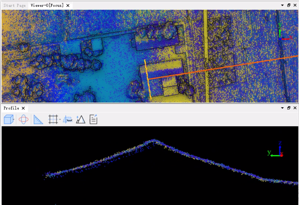
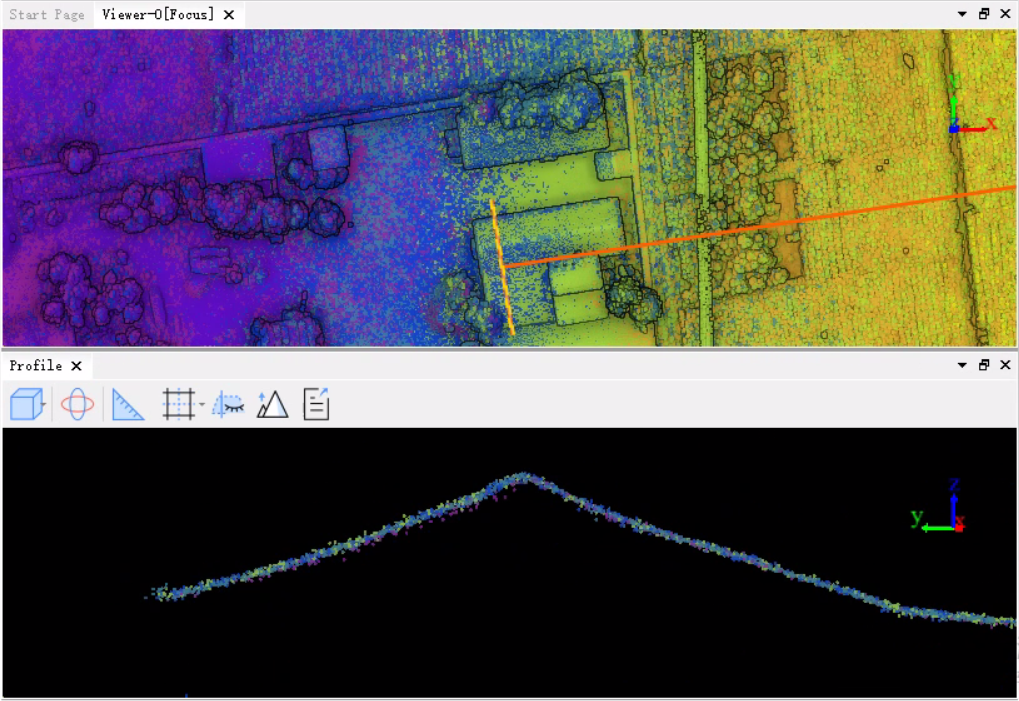
Users can use the profile tool to view the corrected results, as shown in the figure.
Parameters Settings
- Adjust
- ΔX/ΔY/ΔZ:Position component of trajectory correction.
- ΔRoll/ΔPitch/ΔHeading:The angular component of trajectory correction.
- Spline Time Interval:The trajectory fluctuates based on the set time interval, with higher frequencies for shorter intervals. If the trajectory error has significant local shaking, a shorter interval can be set, otherwise a longer interval should be used. The default value is effective for most data.
Output Path:The storage path of the output files after the LiDAR360 function runs. The output files include: corrected point cloud, corrected flight trajectory, and quality statistics HTML report.
Note:In principle, the input for this function requires the entire flight line file used for collecting point cloud data. However, if there is no complete flight line file available, multiple POS files that have been clipped to the flight line can also be used. It is crucial that the GPS time of the point cloud data matches that of the flight line to ensure that after correction, there will be no layering effect in local areas.
Multiple flights Trajectory Adjustment
Multiple flights Trajectory Adjustment is a repeated operation of single flight line leveling, which means adding multiple flights that need to be leveled repeatedly to the interface, checking the trajectory components that need to be corrected, setting the time interval for the trajectory fluctuations, clicking OK, and the software will automatically carry out multiple flights and correct the point cloud data.
Use the Profile Tool to view and adjust correction results, as shown in the figure.
Note:For each flight, its corresponding trajectory and point cloud data must be added, otherwise adjustment calculation cannot be performed.
Mirror Angle Correction
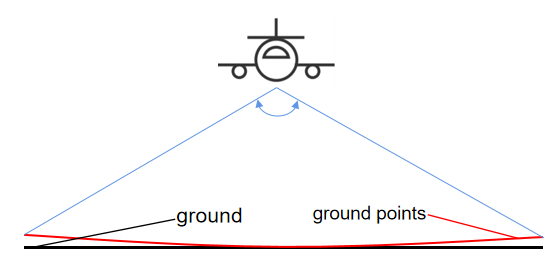
Mirror angle error refers to the scanning angle error of LiDAR scanner, which is caused by insufficient precision of scanner components or complex scanning structures, and is more likely to occur in lightweight and low-cost scanners like the Risley Prism-Based Livox Mid-40. This error may cause point cloud deformation, and the longer the ranging distance, the more obvious the point cloud deformation will be. It has a greater impact on the accuracy of the point cloud position, resulting in point cloud gap in the cross-sectional point cloud along the scanning direction. Correcting the mirror angle error can improve the accuracy of point cloud on the edge of flight strips.
The coordinates of the laser points in the scanner coordinate system are denoted as $X = \begin{bmatrix} x{s} & y{s} & z{s} \end{bmatrix}^T$, where the azimuth angle of the outgoing light beam is denoted as $\Omega$ and the elevation angle is denoted as $\Phi$. Specifically, $\Omega$ can be obtained from $arctan(y{s}/x{s})$, while $\Phi$ can be obtained from $arccos(z{s}/||X||{2})$. Since the change in scanning angle mainly affects the azimuth angle, the elevation angle is less affected, and therefore the scanning angle error is mainly reflected in the azimuth angle error. To correct for the scanning angle error, the azimuth angle is divided into $N$ groups at regular intervals of $1\degree$, with the correction quantity for the $i$th group denoted as $\Delta{i}$. The corrected coordinates of the laser points in the scanner coordinate system after the azimuth angle correction can be expressed as:
$\hat{X} =$ $||X||_{2} \begin{bmatrix} sin(\Omega+\Delta_i)cos\Phi & sin(\Omega+\Delta_i)sin\Phi & cos(\Omega+\Delta_i) \end{bmatrix}^T$
The mirror angle error correction is an optional function of the LiDAR360 software for strip adjustment. The correction can be applied to all angles or only to specified angles outside a certain range.
Please check the Mirror Angle Correction option and select "DJI L1" or "LiAir series" based on the type of laser scanning system being used. If you need to correct all angles, select "All angles". You can also set the range of angles to skip. Mirror Angle Correction is performed per flight mission and not per laser scanning system. For multi-mission flight strip adjustment, if you select the Mirror Angle Correction option, it will be performed for each mission.


If you select mirror angle correction, a histogram of the correction will be generated in the strip adjustment report report.html."
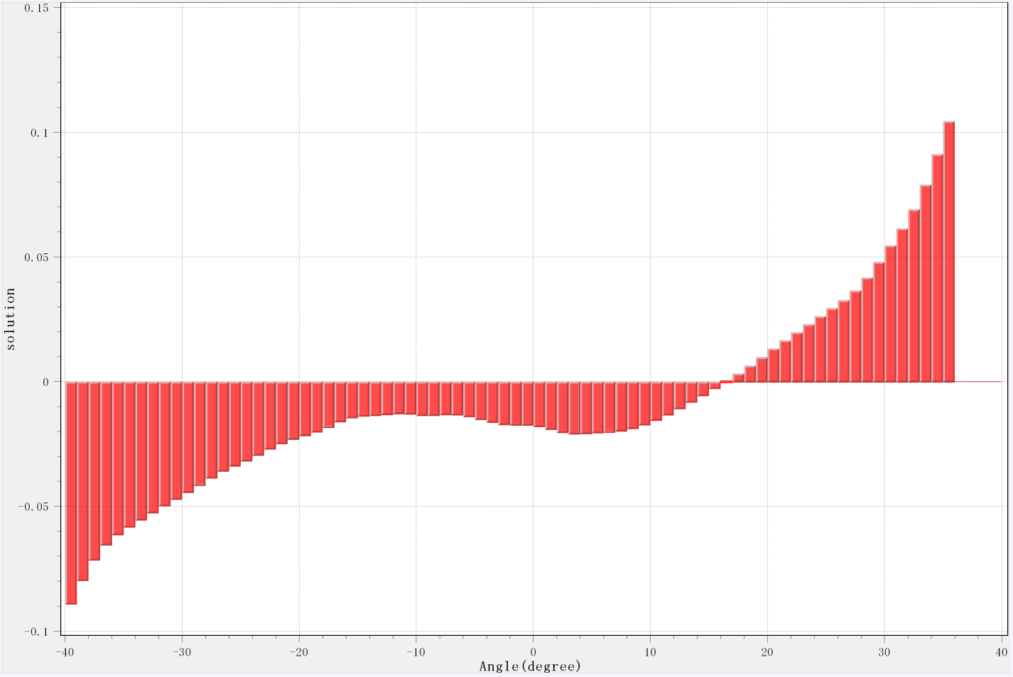
The histogram is the result of smoothing the correction values three times.