Contour Process Tools
The contour processing module can generate contours, create elevation annotation points, detect contour conflicts, and filter by minimum area based on the point cloud data in the scene.
Point Cloud to Contour
Generate contour lines within a selected region of the point cloud data and add them to the current editing object.
Click the left mouse button to select a region, double-click to finish.
A parameter configuration interface will appear. Set the parameters as follows:
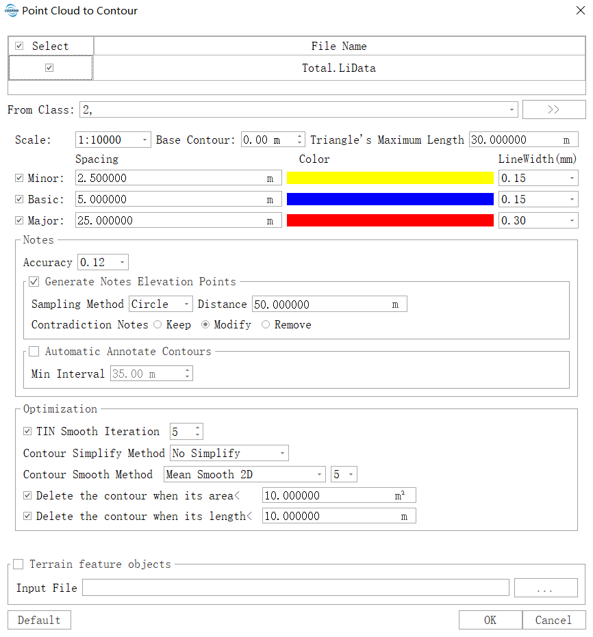
Parameters Settings
Input Data: Ensure that each input point cloud data is the data that has been classified by ground points; the input file can be a single data file or a point cloud data set; the file(s) to be processed must be opened in the LiDAR360 software.
- Scale: There are 11 scales for generating the point cloud, which correspond to different height intervals.
- 1: 500: 1: 500 scale.
- 1: 1000: 1: 1000 scale.
- 1: 2000: 1: 2000 scale.
- 1: 5000: 1: 5000 scale.
- 1: 10000(default): 1: 10000 scale.
- ... ...
- From Class: Point cloud classes that participates in the construction of contour lines.
Base Contour (m)(default value is "0"): The elevation of generated contour lines is calculated starting from the base elevation, where contour elevations are integer multiples of the contour interval from the base. For example, with a base of 0 and a contour interval of 10, the contour elevations will be distributed as: 0, -10, -20, -30..., 10, 20, 30...
Triangle's Maximum Length (m)(default value is "30"): In the triangulated network constructed from ground points, if a triangle's side length exceeds this threshold, it will not participate in contour generation. Visually, this manifests as contour interruptions where point cloud voids exceed this threshold. To ensure generated contours remain continuous without interruptions, set this threshold larger than the maximum void size in the ground point cloud.
- Minor Contours (default: checked): Also known as semi-interval contours. These are drawn at half the contour interval when index contours cannot adequately represent certain local landforms. Uncheck if this contour type is not needed.
- Spacing (m) (default: "2.5"): The absolute elevation difference between adjacent half-interval contours.
- Color (default: yellow): Color of half-interval contours, customizable.
- Line Width (default: "1"): Line width of half-interval contours, customizable.
- Classification Code: Adds a classification code attribute to half-interval contours. Defaults to GB/T 13923/2022 standard in Chinese environments, customizable via user-defined settings.
- Basic Contours (default: checked): Also known as basic contours. These are surveyed at the basic contour interval and serve as the primary contours representing landform morphology. Uncheck if this contour type is not needed.
- Spacing (m) (default: "5"): The absolute elevation difference between adjacent index contours.
- Color (default: blue): Color of index contours, customizable.
- Line Width (default: "2"): Line width of index contours, customizable.
- Classification Code: Adds a classification code attribute to index contours. Defaults to GB/T 13923/2022 standard in Chinese environments, customizable via user-defined settings.
- Major Contours (default: checked): Also called accentuated contours. These are drawn every fourth index contour starting from the datum elevation to facilitate elevation reading. Uncheck if this contour type is not needed.
- Spacing (m) (default: "25"): The absolute elevation difference between adjacent thickened contours.
- Color (default: red): Color of thickened contours, customizable.
- Line Width (default: "3"): Line width of thickened contours, customizable.
- Classification Code: Adds a classification code attribute to thickened contours. Defaults to GB/T 13923/2022 standard in Chinese environments, customizable via user-defined settings.
- Notes Settings:
- Generate Notes Elevation Points (default: checked): Creates elevation points for topographic map output.
- Classification Code: Adds a classification code attribute to elevation annotation points. Defaults to GB/T 13923/2022 standard in Chinese environments, customizable via user-defined settings.
- Sampling Method: Options include circle, grid, and diamond sampling.
- Sampling Distabce: Distance between adjacent sampled annotation points.
- Contradiction Notes: Handling method for conflicting annotation points. Options: Keep (retain originally sampled elevation points), Modify (adjust elevations based on adjacent contours), Delete (remove conflicting points).
- Automatic Arotate Contours: Creates labels indicating contour elevations.
- Interval: Distance between adjacent labels on the same contour line.
- Generate Notes Elevation Points (default: checked): Creates elevation points for topographic map output.
- Optimization: Settings for optimizing generated contours, including smoothing.
- TIN Smooth Iteration: Applies only terrain smoothing (not contour smoothing), producing smoother results without intersection risks.
- Contour Simplify Method:
- Regular Sampling: When regular simplification is enabled, sets the sampling distance along contours.
- Contour Smooth Method (default: No smooth): Options include mean smoothing (3-point, 5-point, 7-point), iterative Bessel smoothing, iterative cubic B-spline smoothing, iterative cubic spline smoothing, FEM-based smoothing, and iterative tension-continuous deviation spline methods.
- Delete the contour when its srea < (m²) (default: "25"): Closed contours with an area smaller than this threshold are deleted.
- Delete the contour when its length < (m) (default: "5"): Open contours shorter than this threshold are deleted.
- Output Format:
- Generate Shp (default): Produces contour files in Shp format, with attribute tables containing line type, width, color, and elevation values.
- Polyline (default): Line type in Shp files is 2D.
- Polyline25D: Line type in Shp files is 2.5D.
- Generate DXF: Produces contour files in DXF format.
- Generate Gpkg: Produces contour files in Gpkg format.
- Generate Shp (default): Produces contour files in Shp format, with attribute tables containing line type, width, color, and elevation values.
- Output Path: Directory to save generated contour files.
Default Values: Click to restore all parameters to default settings.
After configuring the parameters, click OK to generate the contours and add them to the scene. To save to a file, click Save.
Generate Elevation Annotation Point
Generate elevation points for terrain map output based on the point cloud and contours.
Click the left mouse button to select a region, double-click to finish.
A parameter interface will appear. Set the point cloud and elevation point radius.
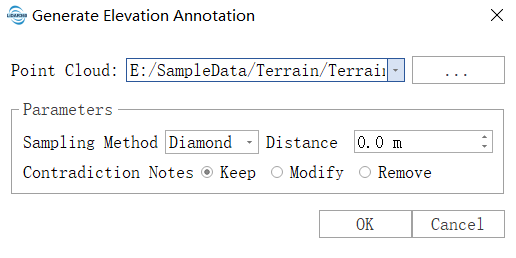
- Input Point Cloud Data: The input file is a single point cloud data file.
- Sampling Method: Includes circular, grid, and diamond sampling methods.
- Sampling Distance: The distance between adjacent sampled annotation points.
- Contradiction Notes: Method for handling Contradiction Notes points. Options: Keep (retains originally sampled elevation annotation points); Modify (adjusts Contradiction Notes point elevations based on adjacent contour lines); Delete (removes Contradiction Notes points).
- Input Point Cloud Data: The input file is a single point cloud data file.
Click OK to generate the elevation annotation points and add them to the scene. To save to a file, click Save.
Check Contour Consistency
If the current contour objects contain contour data and elevation points, contour conflicts can be detected. The results will be marked in the scene (red circles) and displayed in the right panel with detailed conflict information:
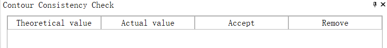
- Theoretical Value: Theoretical height values of conflicting points based on point cloud calculations.
- Actual Value: The actual height values of the conflicting points, i.e., the z-values of the current points (vector entities).
- Accept: Click to remove the circular marking in the scene.
- Delete: Delete the selected elevation annotation points.
Click on a row in the table to highlight the corresponding point in the scene, and double-click to center the point in the scene.
Accepting or deleting will not modify the file. To save changes, click Save. The circular or highlight effects will not be saved to the file.
Filter Minimum Area
Filter out contour entities with an area smaller than a given value, marking them as selected in the scene.
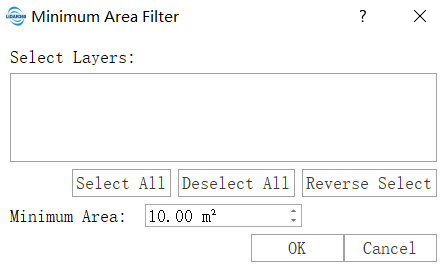
- Select Layers: The layer to be used for filtering; layers not selected will not be processed.
- Minimum Area (m²): Filter out data with an area smaller than this value.
Only closed contours are considered; open contours are not processed.
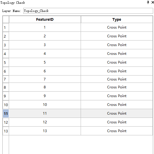
Topological Check
Check for intersection errors in contour points in the scene and mark them as conflicts in both the table and the scene.