Volume To Ref Plane
Steps
- Click the Volume To Ref Plane
 button under Measure to open the volume measurement dialog.
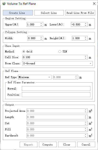
Parameter Settings
Create Line: Manually create a reference line.
Select Line: Select an existing line with the mouse.
Read Line From File: Read line geometry from an external file. Supported formats: .dxf, .shp, .txt.
Region Settings:
- Upper (Δ): Upper range relative to the highest point of the line vector. For example, if set to 1.5, the maximum Z of extracted points will be the highest Z of the line vector + 1.5.
- Lower (Δ): Lower range relative to the lowest point of the line vector. For example, if set to -0.5, the minimum Z of extracted points will be the lowest Z of the line vector - 0.5.
Polygon Settings: Polygon formed by expanding the line vector with width and height.
- Width: Lateral range of the line vector. For example, if set to 2.0, the planar range extends 2.0 meters to both sides of the line.
- Height (Δ): Vertical offset of the polygon relative to the line height, after width expansion, used to control the polygon’s position in the Z direction.
For trenches, due to irregular soil piles and edges, directly creating a polygon can be difficult. Therefore, polygons are generated by expanding centerlines (trench or pipeline) for volume measurement.
Basic Input: Set basic input parameters.
Method: Base method for volume calculation.
- Grid Method: Faster but less accurate than TIN.
- TIN: Slower but more accurate.
Cell Size: Minimum calculation unit size. Smaller values increase accuracy but are more sensitive to noise and slower; larger values reduce accuracy but are less affected by noise.
- For small features such as trenches or vehicles, use 0.1 m or less (not recommended below 0.02 m to avoid holes caused by sparse points). Pre-filter noise for more accurate calculation.
From Class: Point cloud categories to include in the calculation.
Helps effectively filter out noise.
Reference Plane: Defines the reference surface for cut and fill calculation.
- Reference Type:
- Minimum (default): Uses the minimum Z of the outer contour.
- Fitted Plane: Best-fit plane based on selected points.
- Custom: User-specified height as reference plane.
- Three-Point Plane: Pick three points on the point cloud to define a plane.
- Point Cloud Fitting: Hover over points and select with left-click; the fitted plane becomes the reference.
- Ref Plane Parameters: Displays parameters of the reference surface.
- Normal: Normal vector of the plane. Minimum and Custom methods use a horizontal plane; others use the fitted plane normal.
- Position: A point on the reference plane.
- Reference Type:
Create Line Mode: Click Create Line, then left-click at least 2 points in the 3D window to define the area. Double-click to finish. The selected area is drawn as a red solid line.
- Select Line Mode: Left-click an existing line.
- Read Line From File: Click Read Line From File, select a .shp, .dxf, or project-matched geotag.txt file. The software reads the align-x, align-y, align-z columns by default and fits a reference plane.
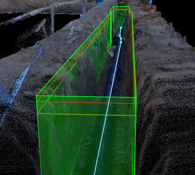
The blue line represents the selected, created, or loaded line vector. The red polygon shows the polygon after width and height expansion. The light green volume is the 3D polygon formed with top and bottom offsets, representing the calculation range. The dark green polygon is the reference plane generated from the red polygon using the selected reference method (minimum value in the figure).
- Set Cell Size. For trenches, 0.1 or 0.05 m is typical.
- Set the Reference Plane for volume measurement.
- Select From Class as needed.
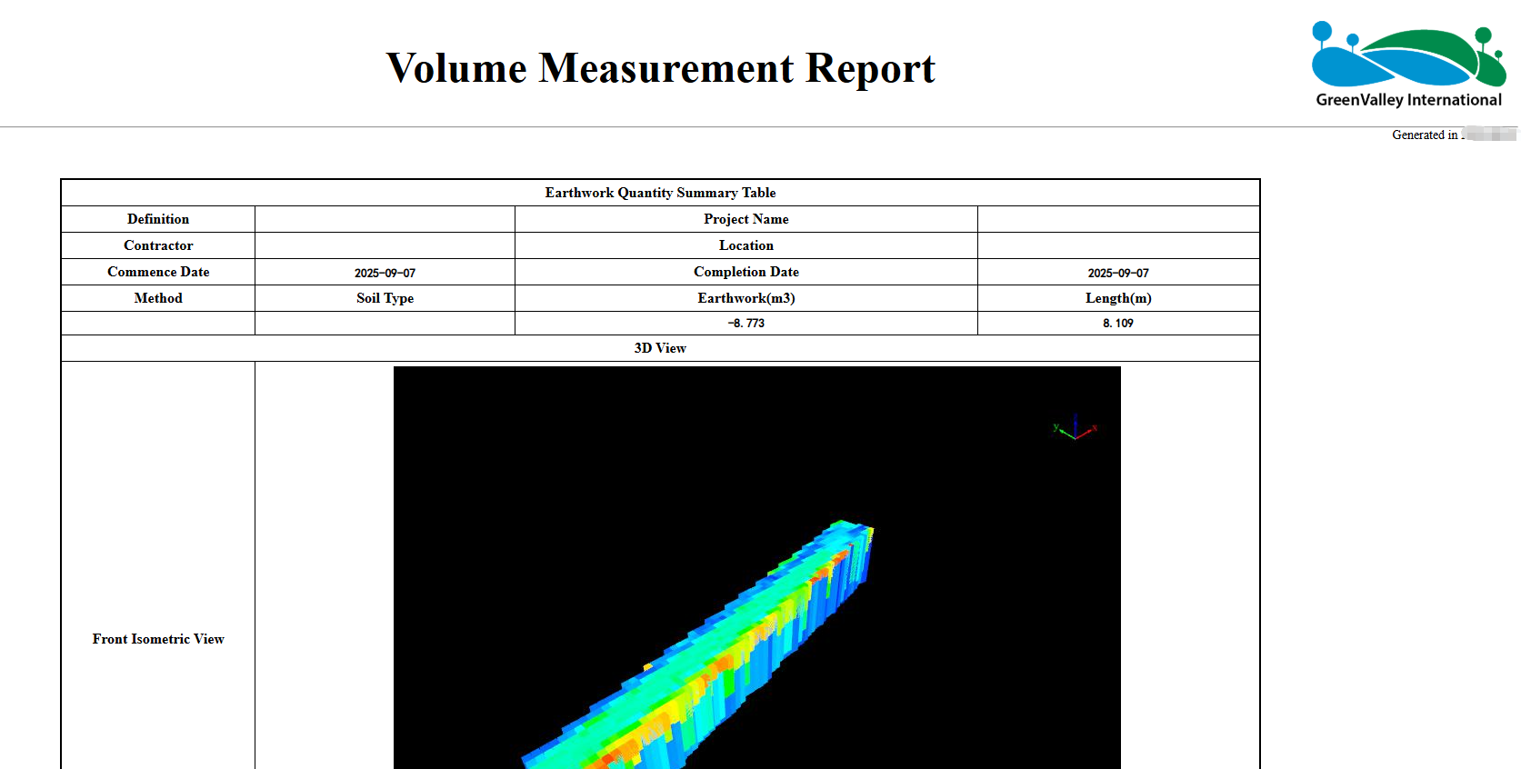
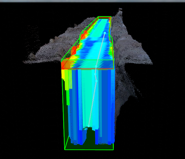
- Click Compute to generate cut, fill, and total earthwork, and display the measured 3D volume in the scene.
- Click Export to open the report dialog. Enter measurement info such as units, location, personnel, or logo.
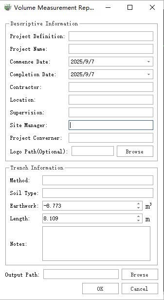
- Click Browse to select the output folder. Click OK to generate the final HTML report.