Volume To Ref Plane
Steps
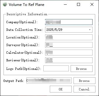
- Click on the Volume To Ref Plane
 button in the Measurement toolset, the volume measurement dialog box pops up.
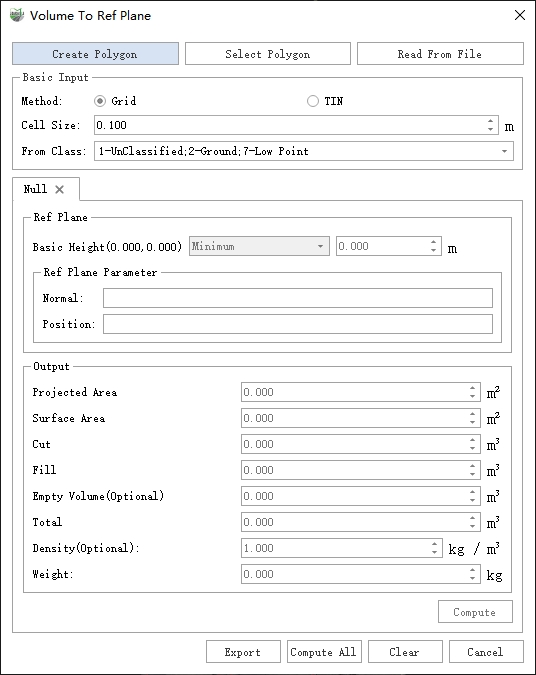
Parameter setting
Create Polygon: Manually create an outer contour on the point cloud.
Select Polygon: Manually select an existing polygon as the outer contour.
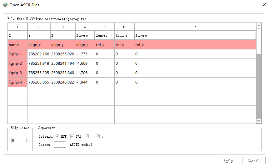
Read From File: Read geometric information of the outer contour from external files. Supports .dxf, .shp, and .txt formats.
Basic Input: Set basic input parameters.
Method: The fundamental method used for volume calculation.
- Grid: Relatively fast speed, but lower precision compared to the TIN method;
- TIN: Relatively slower speed, but higher precision compared to the grid method.
Cell Size: This parameter defines the minimum computation unit size for volume measurement. Smaller values lead to more accurate calculations but are more affected by noise and significantly decrease computation speed; larger values result in less precise calculations but are less influenced by noise.
- For mines and large objects, a size greater than 1.0m is recommended;
- For medium-sized objects such as transport ships and grain silos, a size greater than 0.1m is recommended;
- For small objects like ditches and vehicles, a size less than 0.1m can be used, but it is necessary to filter noise from the input data to reduce errors caused by noise.
From Class: This parameter defines the categories of points in the point cloud that participate in the computation.
Effectively filters out noise.
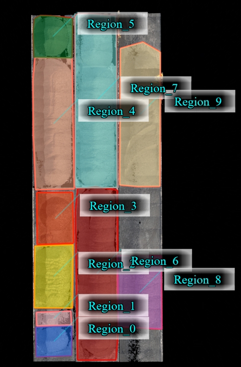
Region Tab: Each valid region generates a separate region page. The default is Null, meaning an empty page.
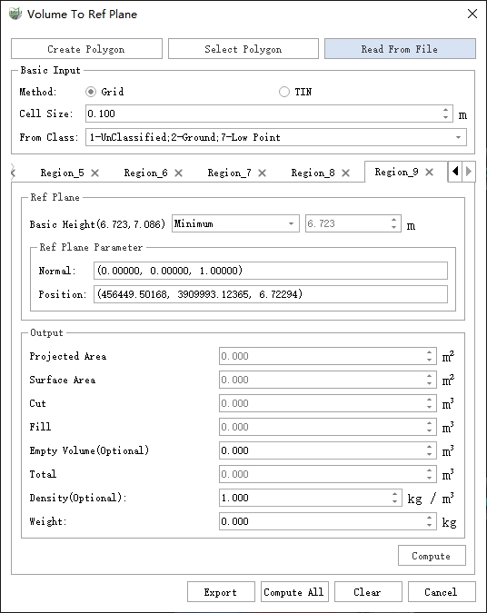
Ref Plane: This parameter defines the reference surface for volume measurement of fill and excavation.
- Ref Type:
- Minimum (Default): Uses the minimum Z value of the outer contour as the height of the plane.
- Fitted Plane: Fits the best plane based on the selected points.
- Custom: User-specified height as the reference surface height for volume measurement.
- Three-Point Plane: Select three points on the point cloud with the mouse to define a plane, which serves as the reference surface.
- Point Cloud Fitting: Automatically enables mouse hover, selecting the fitted plane of the point cloud at the left-click position as the reference surface.
- Ref Plane Parameters: Displays the plane parameters of the reference surface.
- Normal: The normal vector of the reference surface. Minimum value or custom can be set as a horizontal plane, while others represent the normal of the fitted plane.
- Position: A point located on the reference surface.
- Ref Type:
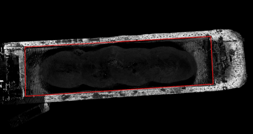
Create Polygon: Click the Create Polygon button, and the window is automatically adjusted to the top view mode. Then, in the window where the point cloud data is loaded, use the left mouse button to consecutively click on the region of interest (to generate a reference plane for volume measurement, select at least three points). Double-click the mouse to end the selection, and the selected area is outlined in red dashed lines in the scene."
Note:
1、If GCP computation has been performed on the data, you should choose the geotag_optimization.txt file after GCP registration. At this point, a file settings list will appear. You need to select the X, Y, and Z columns corresponding to the outline range of the current volume measurement data, and skip the first row.
2、When using a device for field control point acquisition, it is only necessary to hit the target measurement object's footprint. For example, for a sand barge, hitting four intersection points is sufficient.
3、Before volume measurement, it is necessary to use the cleaning tool to remove excess point clouds and noise in order to improve calculation accuracy.
4、Supports importing external vector formats (shp, dxf) for volume measurement.
Set the cell size. For sand barge volume measurement, a cell size of 0.1 or 0.2 is generally suitable.
Set the reference surface for volume measurement. The calculation methods for the reference surface include minimum value, average value, and user input. When choosing a file for volume measurement, the average value is generally selected for the reference surface.
Select source categories to participate in the calculation based on your requirements.
The volume measurement methods include TIN and grid. Unchecking TIN selects the grid method.
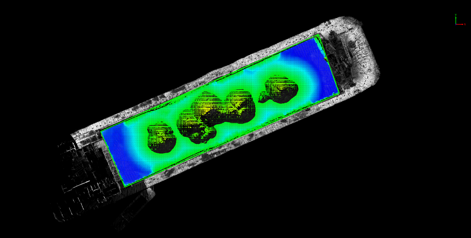
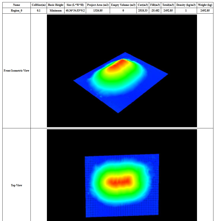
Click the calculate button to generate cut, fill, and cut-fill results. At the same time, the space occupied by the current measurement data is displayed in the scene, as shown in the figure.

If there are trajectory lines in the report that you don't want to display, you need to manually turn it off before exporting the report.