ModelBuilder terminology
Logical Diagram
The model logical diagram represents everything you see when editing a model in ModelBuilder, including the appearance and layout of tools and parameters within the model.
Elements
Model elements are the basic building blocks of a model. They are mainly divided into three types: data processing tools, data variables, and connectors.
- Data processing tools perform various operations on 2D/3D data or tables. Once a tool is added to the model, it becomes a model element. You can open the tool dialog for any data processing tool in the model to configure its execution parameters.
Data processing tool
A data variable is an element in the model used to store inputs and outputs.
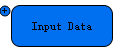
Data variable
In LiDAR360MLS, a small circle with a '+' symbol is drawn in the upper-left corner of a data variable to indicate that it is an input variable with no preceding tool. A small circle with a '−' symbol indicates that the data variable is an output of a tool.
Connectors are used to link data variables to tools. The arrow on the connector indicates the direction of data flow.

Connector
Workflow and Status
A model workflow consists of tools and their associated data variables. Connectors indicate the processing sequence. Multiple workflows can be linked together to create a larger workflow.
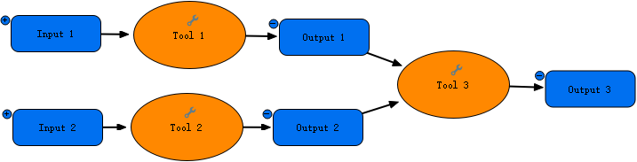
Tool workflow
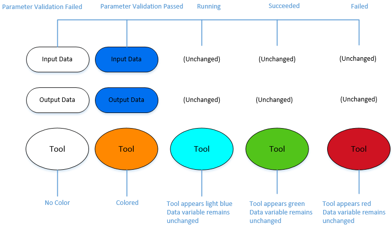
The workflow in a model can be in one of five states: parameter validation failed, parameter validation passed, running, succeeded, or failed.
Parameter Validation Failed
When a tool or data variable is first dragged into ModelBuilder, the workflow is in the parameter validation failed state because required parameter values have not yet been specified. The tool and its inputs and outputs appear white.
Parameter Validation Passed
Once all required parameters for a tool are correctly set, the workflow enters the parameter validation passed state. All model elements in the workflow appear orange.
Running
If a model tool is light blue, the workflow is in the running state.
Succeeded
If the model is run in ModelBuilder and the tool appears green, it indicates that the workflow has run successfully and returned results.
Failed
If the model is run in ModelBuilder and the tool appears red, it indicates that the workflow has run but failed to return results.
Workflow Status Display
Data Variable Types
Input and output variables in a model can be single-value or multi-value. Both types support a specific data type. You can create an input parameter element by dragging a variable from the floating input box in the upper-left corner of the model view into the ModelBuilder view. Alternatively, you can right-click a tool and use the Get Parameters submenu to create the corresponding input parameter element.
Validation
Model validation ensures that all model variables and tool parameters are valid and that the corresponding tools have the necessary module licenses activated.
Layout
To arrange elements in the model, select an element and move it to the desired position, or use the Auto Layout button on the ModelBuilder tab for automatic arrangement.
Delete Outputs
You can delete results generated by the previous model run to ensure that the outputs of tools in the next run do not conflict with existing data.