Add and connect data and tools, and modify elements
Data processing models are composed of model elements connected together to form a workflow. You can add data processing tools and data, connect them, and modify the position and properties of the elements.
Add data
There are three ways to add data to a model: from the Catalog tree, from a data processing tool’s right-click parameter option, or from the input pop-up box.
When data is added to a model, a data variable is created and displayed as a blue oval. A data variable contains a description of the data, not the data itself. ModelBuilder stores descriptive information about the data in the variable, such as the data name, description, format, and geometry type (for feature classes).
Add from the Catalog tree
From the Catalog pane, you can drag one or more datasets into the ModelBuilder view, including point clouds, feature classes, tables, rasters, and tracks.
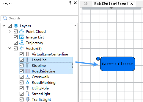
Add data to a model from the Catalog pane
Add from a data processing tool’s right-click Get Parameters
In the ModelBuilder view, right-click a data processing tool element. From the Get Parameters submenu in the context menu, select an enabled option. Left-clicking creates a specified input variable and automatically creates a connection from the variable to the tool.
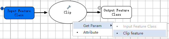
Add data to a model using a data processing tool’s right-click Get Parameters
##### Add from the input pop-up box
Drag Input Data ![]() from the floating input box in the upper-left corner of the ModelBuilder view into the ModelBuilder view.
from the floating input box in the upper-left corner of the ModelBuilder view into the ModelBuilder view.
Data added from the floating input box initially has no data selected, so the data variable element appears white.
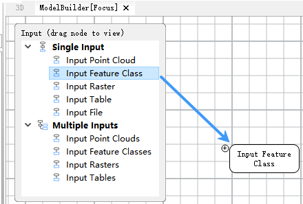
Add data to a model from the floating input box
For single-value input nodes, only one dataset can be selected and added for each input type; for multi-value input nodes, multiple datasets can be selected and added for each input type.
Input Point Cloud: Can be dragged into the model as the input point cloud for a point cloud data processing tool.
Input Feature Class: Can be dragged into the model as the input feature class for a vector data processing tool.
Input Raster: Can be dragged into the model as the input raster for a raster data processing tool.
Input Table: Can be dragged into the model as the input table for a table data processing tool.
Input File: Can be dragged into the model to connect to data processing tools that require a file as input.
Note: Specially, tools related to vector projection and coordinate transformation require using an input file, as the entire vector file needs to be transformed as a whole; an input feature class cannot be used.
When dragging input data from the floating input box into ModelBuilder, a parameter settings dialog appears. You can modify the default settings in this dialog to customize your input, or simply accept the default parameters and click OK.
The following provides examples for dragging Input Feature Class and Input File, explaining some of the settings in this dialog.
- Dragging an Input Feature Class
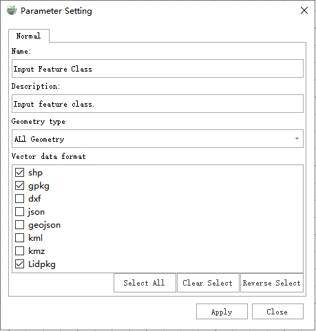
Input Feature Class Parameter Settings Dialog
Parameter description:
Name: The name of the data variable created in the model after dragging in the input feature class. This name must be unique within the model.
Description: Used to describe the meaning of the current parameter.
Geometry Type: Specifies the acceptable input geometry types for the feature class. Options include All, Point, Line, and Polygon, and multiple selections are supported.
Vector Data Format: Limits the vector data formats supported by the data variable created in the model. When connecting the data variable to a data processing tool, the connection will fail if the variable does not include a format supported by the tool.
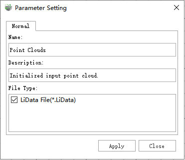
- Dragging an Input File
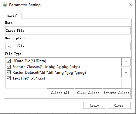
Input File Parameter Settings Dialog
Parameter description:
Name: The name of the data variable created in the model after dragging in the input file. This name must be unique within the model.
Description: Used to describe the meaning of the current parameter.
File Type: Limits the file formats supported by the data variable created in the model. When connecting the data variable to a data processing tool, the connection will fail if the variable does not include a format supported by the tool. If the data processing tool requires a file type other than the default, you can click the '+' button on the right of the file list to define and add a new format in the pop-up format definition dialog.
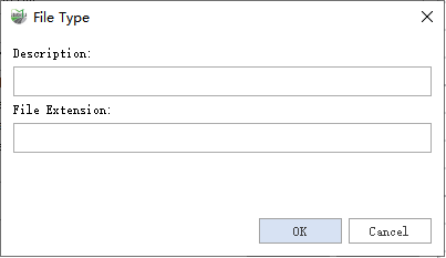
Add File Type Dialog
Where:
Description: Describes the currently defined file type.
File Extension: The file suffix. For example, if the description is "Text File" and the file extension is "txt," a file type with the .txt extension is created.
Dragging the floating input box near the edge of the ModelBuilder view will hide it. Click the hidden block to display it again when needed.
Modify a data variable
To view or change the value of a data variable, double-click the variable to open the variable value dialog.
The following example uses single-value and multi-value input point cloud data variables.
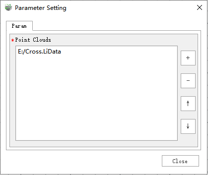
Modify the value of a multi-value input point cloud data variable
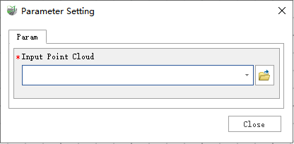
Modify the value of a single-value input point cloud data variable
For a multi-value input point cloud data variable, you can click the '+' and '−' buttons on the right side of the variable value box to add or remove selected data. For a single-value input, you can modify the input using the Open button on the right, select an existing point cloud from the current project via the drop-down menu, or quickly edit the data path directly.
Note: When a data variable is the output of a previous data processing tool, some tools may restrict modifications to the output, allowing only the default output. In this case, you cannot change the value of the data variable.
To view or modify the properties of a data variable, right-click the variable and click Properties. The property dialog that appears is similar to the dialog displayed when dragging a data variable from the floating input box into the model, except that the file type cannot be modified at this stage. After making changes, click Apply to complete the modification.
Modify the properties of an input point cloud data variable
Add a data processing tool
In the Geoprocessing Toolbox pane, you can select or search for the required data processing tool and drag it into the ModelBuilder view.
When a data processing tool is added to a model, certain scenarios may trigger automatic strategic connections and automatic strategic layout, as follows:
- If the tool is dragged onto the output element of a previous tool or an input element, and the system detects that the underlying data variable meets the input data format requirements of the dragged tool, a connection from the data variable to the tool is automatically created, along with the tool element and its associated output variables. If the dragged tool requires multiple inputs, a selection menu will appear prompting the user to choose an input. Once the user selects one, the system will automatically create the connection from the data variable to the tool, along with the tool element and related output variables.
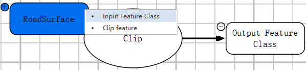
Drag a tool that requires multiple inputs onto a data variable
- If a tool is dragged onto the output element of a previous tool or an input element and automatic connections are triggered, the strategic layout for the tool element and output data variable will also be applied.
- When both input and output data variables are created along with connections from input data variables to the tool element and from the tool element to output data variables, neither strategic connections nor strategic layout is triggered.
- If a tool is dragged onto a location that is not a data variable, the system will automatically create all input and output data variables for the tool, along with connections from input data variables to the tool element and from the tool element to output data variables. Strategic connections and strategic layout are not triggered.
- If a tool is dragged onto a data variable that does not meet the tool’s input data format requirements, strategic connections and strategic layout are not triggered.
When a data processing tool is added to a model, it often appears white because some required parameters have not been set. After setting the necessary tool parameters and passing the automatic parameter validation, the tool changes to orange, indicating that it is ready to run.
It is recommended to drag tools onto appropriate data variables when adding them, as this greatly facilitates editing your model diagram.
Modify tool parameters
To modify a tool’s parameters, double-click the tool element in the model. This opens the tool parameter settings dialog, which is generally similar to the dialog that appears when you double-click the tool in the Toolbox. The main difference is that if the dialog contains input or output data controls, their modification may be restricted. After adjusting the parameters, click OK to save the changes. Clicking OK does not run the tool; it only saves the parameters. To run the tool, click the Run button ![]() on the ModelBuilder tab.
on the ModelBuilder tab.
Connect data and tools
You can specify data for a data processing tool by creating connections between variables and tools in the model. In addition to the automatic strategic connections described in Add Data, you can also draw connections interactively: without selecting a tool, left-click a data variable, hold the mouse button, drag to the tool, and release the button.
To draw a connection interactively, follow these steps:
1.Deselect the variable you want to connect to the tool.
Left-click on a blank area to deselect all model elements.
2.Hover over the variable you want to connect.
3.Press and hold the left mouse button, and drag the pointer to the tool.
4.When the pointer is over the tool, release the left mouse button. A menu will appear to select the input. Left-click an enabled input parameter to connect the variable to the tool.
Note:
a. If the tool has only one input and the data variable matches its type and filters, the input selection menu will not appear.
b. If the tool has only one input and the data variable does not match its type or filters, the connection will fail, and a failure reason will be displayed automatically.
c. If the tool has multiple inputs and the data variable does not match any input’s type or filters, or if the corresponding input already has a connection, the input in the selection menu will appear grayed out and cannot be selected.
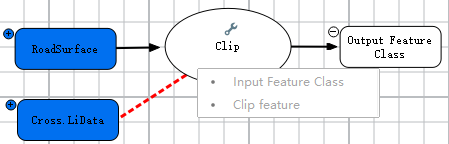
Connect an unsupported data variable to a tool element
A data variable can be connected to multiple tools, and multiple data variables can be connected to a single tool. To check whether a tool supports multiple data variable connections, hover the mouse over the tool variable and view the information in the pop-up tooltip.
The following is an example of a tool that supports multiple input data variables.
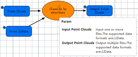
View tool variable input and output parameter information
Move elements
To move a model element, select the element. When selected, the element’s border turns green. Hover the mouse over the center of the element, press and hold the left mouse button, and drag the element to any desired location in the model.
Rename elements
When elements are added, default names for tools and iterators are automatically generated by ModelBuilder. If a name already exists in the model, a unique number is appended to it. To rename a model element to a unique name, right-click the element and click Properties, then follow the steps under Modify a data variable. In the Properties window, change the name to a unique one.
Select elements
When a data variable or tool element is selected, its border appears green. When a connection line is selected, it appears red. There are several ways to select elements:
Click selection: Left-click any element in the ModelBuilder view.
Drag selection: Left-click in an empty area of the ModelBuilder view, hold, and drag to draw a transparent box. All elements that intersect the box will be selected.
Select All: Click Select All ![]() in the Mode group on the ModelBuilder tab to select all elements in the model.
in the Mode group on the ModelBuilder tab to select all elements in the model.
Delete elements
Elements can be deleted when selected. There are two ways to delete elements:
Keyboard shortcut: Press the ‘Delete’ key on the keyboard. A prompt will appear to confirm deletion of the selected elements.
Menu deletion: Click the Delete ![]() button in the Mode group on the ModelBuilder tab to delete all selected elements in the model.
button in the Mode group on the ModelBuilder tab to delete all selected elements in the model.