Model diagram appearance
You can change the appearance of the model diagram using the following methods: move elements, use Auto Layout, Undo, Redo, display at actual scale, Fit to View, Zoom In, Zoom Out, and Grid. Modifying the model diagram appearance helps make your model easier to read and understand.
Layout
- You can manually arrange elements in the model by moving them to a new position. When the model is saved, the element positions are preserved.
- To apply Auto Layout in the model, click the Tool Interface tab, and then in the View group, click Auto Layout
 .
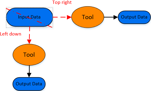
. - You can drag a tool onto a data variable element in the model view. When tool strategic layout is applied, the tool will be positioned according to the following rules:
- If the mouse is closer to the upper-right corner of the data variable when dragging, the tool will be placed to the right of the data variable element, aligned with the horizontal centerline of the data variable’s bounding rectangle.
- If the mouse is closer to the lower-left corner of the data variable when dragging, the tool will be placed below the data variable element, aligned with the vertical centerline of the data variable’s bounding rectangle.
- If the intended layout position is already occupied, a tool added to the right of a data variable will attempt to find a suitable position below the original position; a tool added below a data variable will attempt to find a suitable position to the right of the original position.
Automatic Strategic Layout
Undo and Redo
- On the ModelBuilder tab, in the View group, click Undo
 to revert the model logical diagram to the state before the most recent action.
 - On the ModelBuilder tab, in the View group, click Redo
 to restore the model logical diagram to the state before the last undo action.
Zoom In and Zoom Out
There are two ways to zoom the model logical diagram:
- Scroll the mouse wheel to zoom in or out relative to the cursor position.
- On the ModelBuilder tab, in the View group, click the Zoom In or Zoom Out menu.
Actual
On the ModelBuilder tab, in the View group, click Actual Scale ![]() to display the model logical diagram at the original size of each element.
to display the model logical diagram at the original size of each element.
Global
On the ModelBuilder tab, in the View group, click Fit to View ![]() to scale the model logical diagram to fit the bounding rectangle of all elements.
to scale the model logical diagram to fit the bounding rectangle of all elements.
Grid
Checking Grid displays intersecting gray lines in the model view to assist with editing the model logical diagram. Unchecking it hides the intersecting gray lines.