Section Terrain
For related operations such as section projects, data management, and 2D window display, see Section Analysis.
Prerequisite: After completing the design cross-sections, click the Terrain Section ![]() button to enter the terrain section workflow. Functions such as section measurement, TIN creation, and feature line export become available, and a 2D section display window will pop up.
button to enter the terrain section workflow. Functions such as section measurement, TIN creation, and feature line export become available, and a 2D section display window will pop up.
Only when the terrain section is active can subsequent calculation buttons be used. While the terrain section is active, switching projects or adding/deleting/modifying design data via the catalog is not allowed.
Road Terrain
Road terrain requires both section point clouds and a terrain template, which must be extracted and created in sequence.
- Click the Road Terrain
 button to open the settings dialog.
Step 1: Extract Section Point Cloud
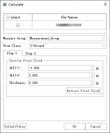
Parameter Dialog
Parameter Description
- Measure Group: Select the measurement data group to be calculated.
- Section Point Cloud: Extracts point clouds according to the design cross-section.
- Thickness: Extract point clouds within the specified thickness of the design cross-section.
- ΔZ(-): Extracts point clouds above the design cross-section Z value. For example, if set to -1.0, point clouds with Z ≥ design Z - 1.0 will be extracted.
- ΔZ(+): Extracts point clouds below the design cross-section Z value. For example, if set to 3.0, point clouds with Z ≤ design Z + 3.0 will be extracted.
- General
- From Class: The point cloud category used to generate the section. If chosen incorrectly, the generated result may be inaccurate.
Click the Extract Point Cloud button to perform cross-section point cloud extraction.
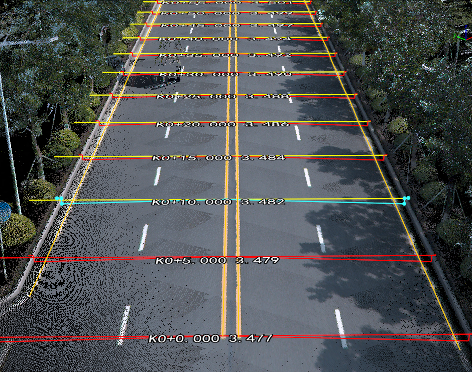
Result Example:
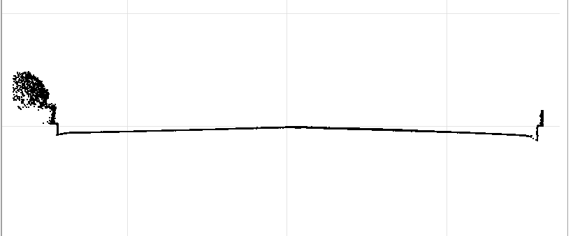
Extracted Cross-Section Point Cloud
Step 2: Set Terrain Template
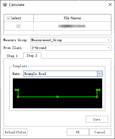
Parameter Dialog
Template: The section terrain uses manually created terrain templates combined with section point clouds to generate measurement cross-sections. Each cross-section shares identical nodes, ensuring precise and strict TIN construction. Two workflows are available:
Manual Creation Work flow
Procedure:
Set the template name to Manual.
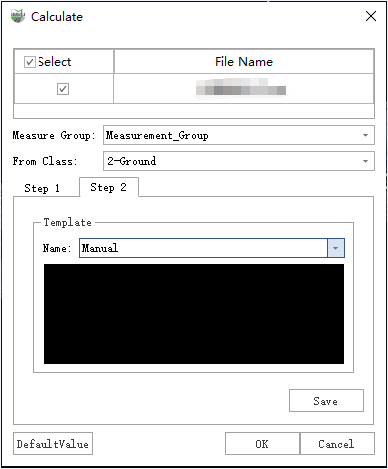
Manual Creation
In the 2D display window, use the Add Section Line Nodes function to draw the terrain template along the extracted section point clouds.
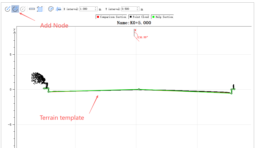
Manually Create New Template
Left-click to add nodes; right-click to undo the last added node.
Save: Save the newly created manual template.
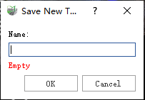
Save New Template
Use Built-in Template – Manual Editing Work flow
Procedure:
- Select an existing stored terrain template, e.g., the built-in "Example Road" (7-point terrain template).
- Use the Edit Section Line Nodes function in the 2D section window to adjust the template so that its nodes match the section point clouds.
Click OK to generate the terrain section.
Road Terrain Result
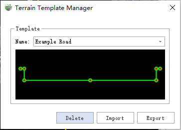
Terrain Template Manager
Browse, delete, import, and export terrain templates.
Road Terrain Result
- Browse: All stored terrain templates can be selectively browsed via the drop down list. The template style is displayed in real time in the preview window below.
- Delete: Click the delete button to remove the currently displayed template. Note: This action is irreversible.
- Import: Used together with Export, allows importing template files exported from other machines via the Terrain Template Manager.
- Export: Used together with Import, allows exporting template files for use on other machines.
Create TIN
- Click the Create TIN button to open the parameter dialog and select the measurement data group to build the TIN.
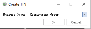
Dialog
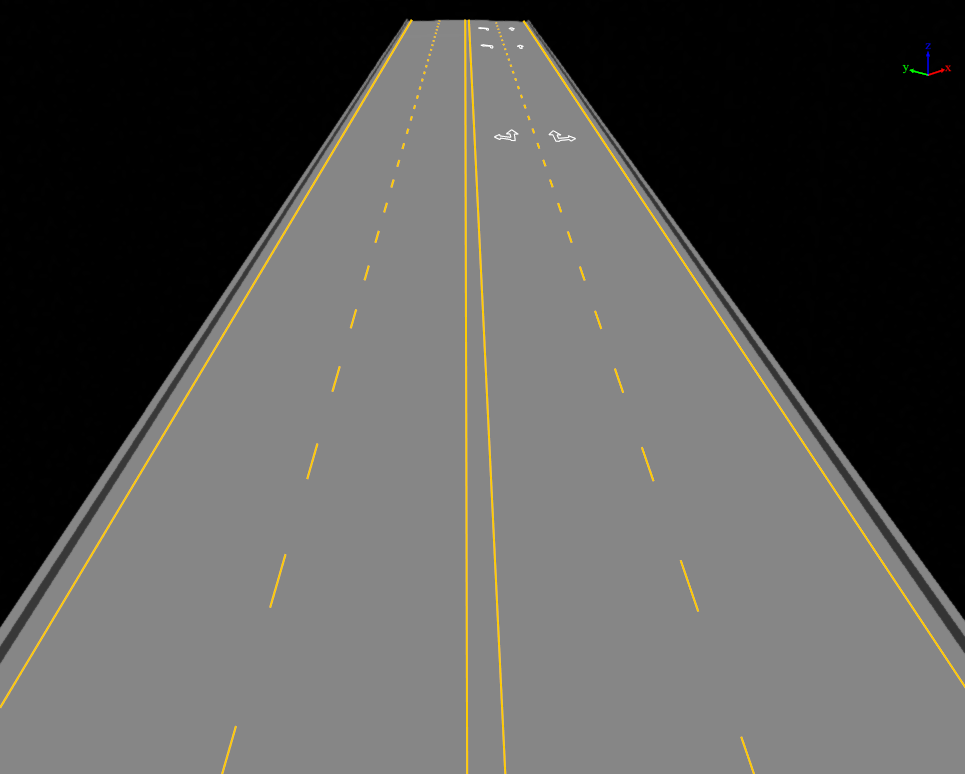
TIN Creation Result
Export Feature Lines
- Click the Export Feature Lines button to open the parameter dialog.
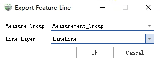
Dialog
Parameter Description
- Measurement Data Group: The measurement data group from which to export feature lines.
- Line Layer: The target layer where the feature lines will be exported.
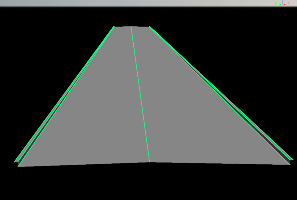
Feature Line Example