Road Design cross section Data Preparation
Design longitudinal Axis Creation
Design

Design Longitudinal Axis
Steps
1.Station Equation Design: A station equation occurs when the route is discontinuous due to local alignment changes, segmented measurements/designs, etc. Based on the magnitude of station changes, station equation are classified into the following two types:
- Long Station Equation: The station before the break is greater than the station after the break.
- Short Station Equation: The station before the break is less than the station after the break.
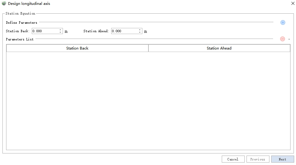
Station Equation
If there are no station equation, proceed directly to the next step. If station equation exist, input the station before and after the break, then click ![]() to add a single station equation. All results will be displayed in the parameter list. Additionally, the dropdown menu supports deletion, clearing, importing, and exporting operations.
to add a single station equation. All results will be displayed in the parameter list. Additionally, the dropdown menu supports deletion, clearing, importing, and exporting operations.
Delete: Delete the currently selected station equation.
Clear: Clear all station equation in the list.
Import: Import a station equation file, supporting both built-in .se format and custom text format.
Export: Export the station equation as a .se file.
After completing the station equation editing, click Next.
2.Horizontal Curve: Used to define the planar position of the longitudinal axis, supporting both the Intersection Method and the Line Element Method for defining the curve. Before introducing the specific parameters, it's necessary to understand the planar coordinate system used for input parameters.
Plane Coordinate System:
NE Coordinate System: Different software may have differences in the direction of the XY axes. In some software, the X-axis points to the north, and in others, it points east (in MLS, the X-axis points east, and the Y-axis points north). To avoid potential input errors caused by the XY coordinate system, this system uses a North-East (NE) coordinate system. Before inputting data, confirm that the design coordinate axis matches the NE system; if not, conversion is required.
Azimuth: Defined as the angle from the north direction, with counterclockwise being positive, ranging from 0-360 degrees.
Note: This is only the coordinate system used for parameter input; the final result of coordinate points will still be in the MLS-defined XY coordinate system.
Intersection Method: Define three types of points: Start Point, Point of Intersection, and End Point. The parameters for each type of point are as follows, where -- is a placeholder meaning no parameter is required.
Intersection Method Parameters Start Point Point of Intersection End Point Start Station -- -- -- Radius -- (N, E) (N, E) (N, E) -- Entry Transition Curve Length (L1) -- -- Exit Transition Curve Length (L2) -- -- Entry Transition Curve Radius (R1) -- -- Exit Transition Curve Radius (R2) -- The Intersection Method can be defined using the following operations:
Add: Add the manually entered point to the list.
Delete: Delete the last point in the list.
Clear: Clear all points in the list.
Import: Import the horizontal curve intersection file, supporting both built-in .hpi format and custom text format.
Export: Export the intersection points list as a .hpi file.
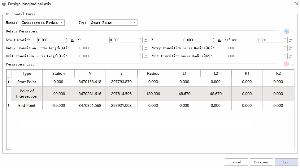
Horizontal Curve (Intersection Method)
Line Element Method: Supports five types of elements: Line, Entry Transition Curve, Circular Curve, Exit Transition Curve, and Incomplete Transition Curve. The parameters for each element are as follows, where -- is a placeholder for no parameter.
Line Element Method Parameters Line Circular Curve Entry Transition Curve Exit Transition Curve Incomplete Transition Curve Start Station Start Station Start Station Start Station Start Station End Station End Station End Station End Station End Station Starting (N, E) Starting (N, E) Starting (N, E) Starting (N, E) Starting (N, E) Starting Azimuth Starting Azimuth Starting Azimuth Starting Azimuth Starting Azimuth -- Turn Turn Turn Turn -- Radius -- Starting Radius Starting Radius -- -- Ending Radius -- Ending Radius The Line Element Method can be defined using the following operations:
Add: Add the manually entered element to the list.
Delete: Delete the last element in the list.
Clear: Clear all elements in the list.
Import: Import the horizontal curve element file, supporting both built-in .hle format and custom text format.
Export: Export the element list as a .hle file.
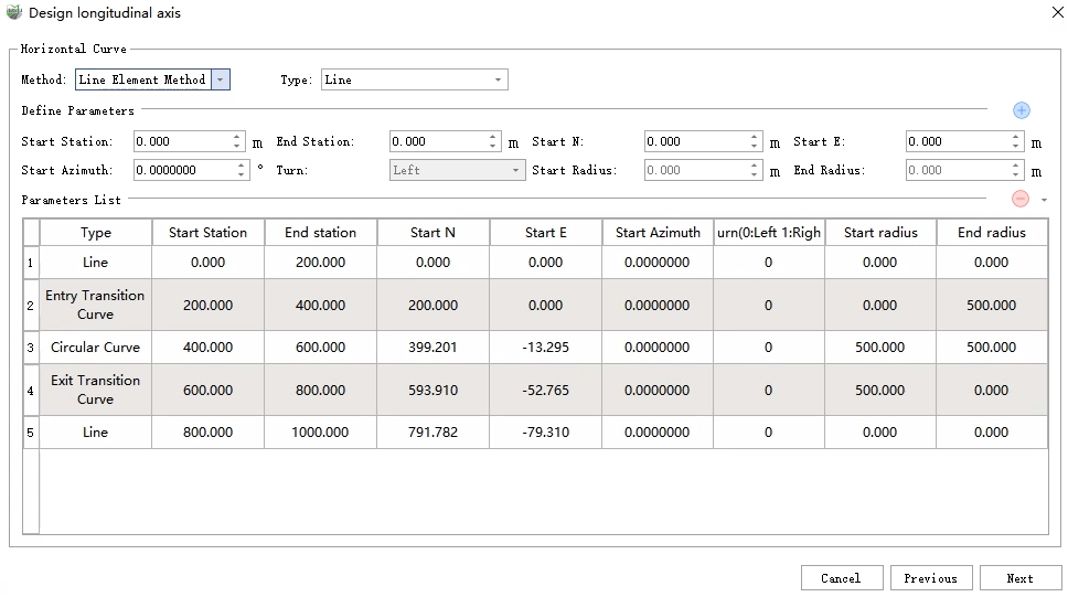
Horizontal Curve (Line Element Method)
After completing the horizontal curve definition, click Next.
3.Vertical Curve: Used to define the elevation of the axis by defining the break slope points' station, elevation, and radius. The following operations can be performed:
Add: Add the manually entered break slope point to the list.
Delete: Delete the last break slope point in the list.
Clear: Clear all break slope points in the list.
Import: Import the vertical curve file, supporting both built-in .vpi format and custom text format.
Export: Export the break slope points list as a .vpi file.
After completing the vertical curve definition, click Finish.
Draw
Steps
1.Click sequentially with the left mouse button. 2.Double-click the left mouse button to finish the creation.
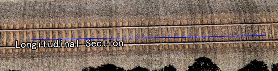
Longitudinal Section
Selection
Design Cross Section Creation
Cross Section Manager
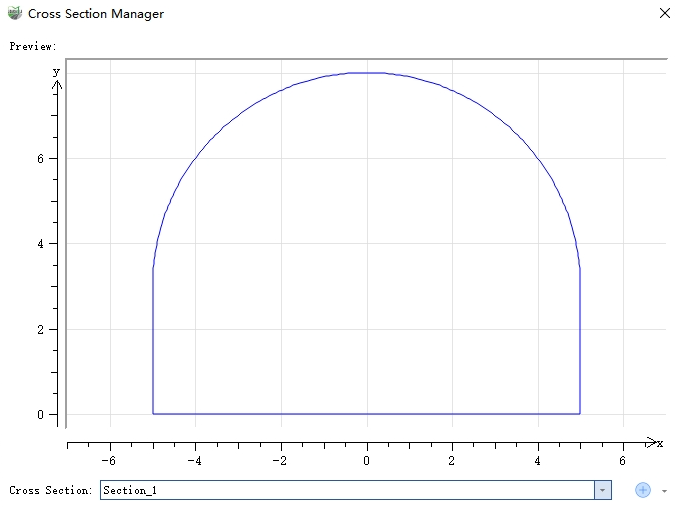
Cross-Section Manager
Editing Operations: The following operations can be used to manage cross-sections.
New: Create a new cross-section.
Edit: Edit the current cross-section, and it will be updated upon completion.
Delete: Delete the current cross-section.
Clear: Clear all cross-sections.
Import: Import an external .cs cross-section file.
Export: Export the current cross-section as a .cs file.
Cross-Section Types
- Single-Centered Arch: Composed of a semi-circular arch top and a horizontal bottom. The radius of the arch and the position of the bottom can be adjusted.
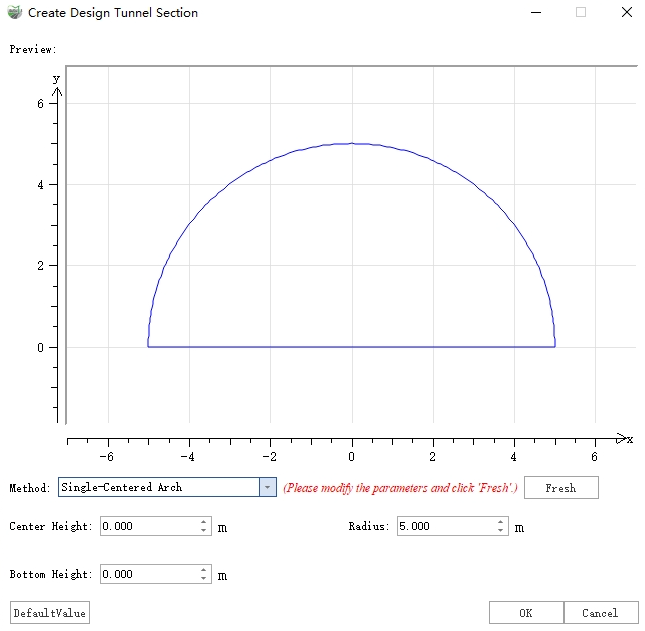
Single-Centered Arch
- Straight Wall Semi-Circular Arch: Composed of a semi-circular arch top, wall, and a horizontal bottom. The radius of the arch, wall height, and bottom position can be adjusted.
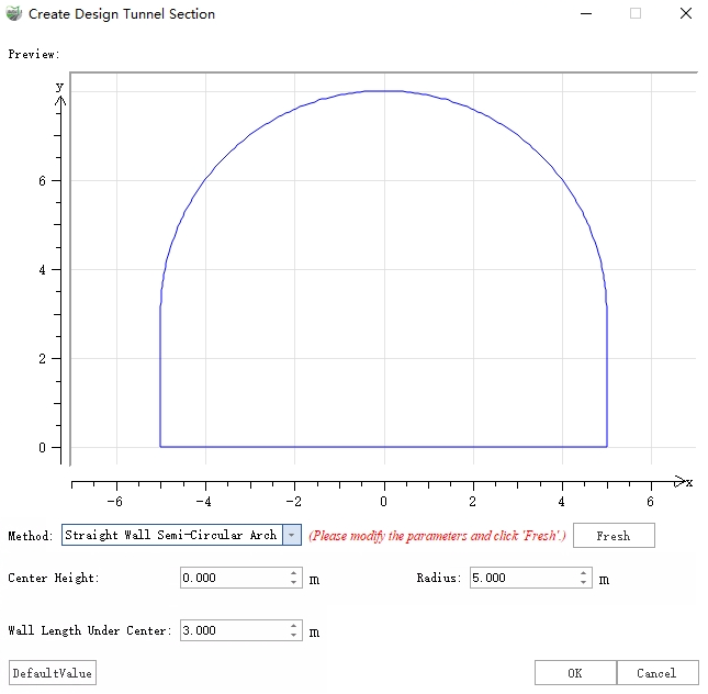
Straight Wall Semi-Circular Arch
- Three-Centered Arch: Also known as a four-centered arch, consisting of the top arch, two wall arches, and the bottom arch, formed by four tangent circles. The center positions and radii of each arch can be adjusted.
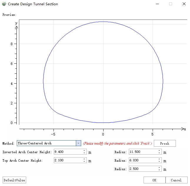
Three-Centered Arch
- Custom: Custom-shaped cross-sections created by combining line elements, supporting two types of elements: Line and Arc.
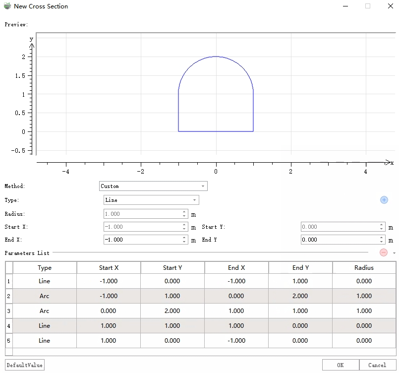
Custom Cross-Section
Automatic
Parameter Dialog
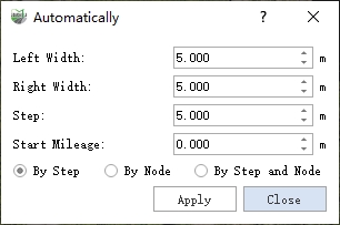
Dialog
Parameter Description
- Left Width: The distance from the leftmost point of the cross section reference line to the vertical reference line, defaulting to "5". If using road attributes for calculation, it should be set to half the lane width.
- Right Width: The distance from the rightmost point of the cross section reference line to the vertical reference line, defaulting to "5". If using road attributes for calculation, it should be set to half the lane width.
- Step: The step length for generating reference cross sections.
- Start Station (default is "0"): The starting station for generating reference cross sections; the station for each cross section will accumulate based on this. The starting station stakes for different sections of the road may vary, and cross sections are named by default in the form of stake km + m. Users can modify the names of the cross sections as needed.
- By Step: Generate reference cross sections at specific step lengths.
- By Node: Generate reference cross sections only at nodes, where nodes refer to the nodes of the vertical reference line itself.
- By Step and Node: Generate reference cross sections at specific step lengths while also processing the nodes.
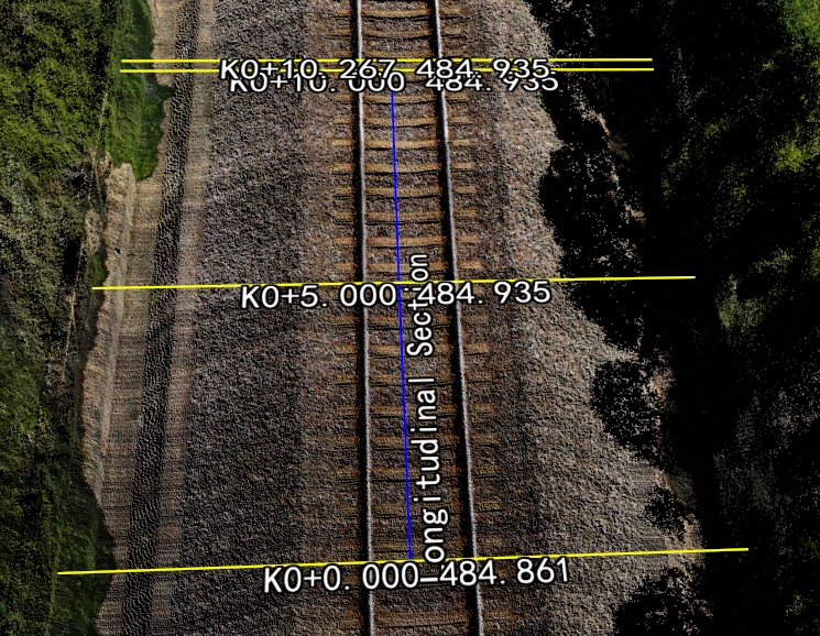
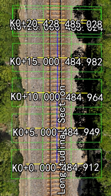
Effect Diagram
The blue vector line represents the manually drawn design vertical axis, while the yellow line represents the automatically generated cross section reference line according to the specified step length.
Manual
Parameter Dialog
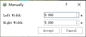
Parameter Dialog
Parameter Description
- Left Width: Default is 5.0 meters; this is the distance from the leftmost point of the design cross section line to the design longitudinal axis.
- Right Width: Default is 5.0 meters; this is the distance from the rightmost point of the design cross section line to the design longitudinal axis.
- Accept/Cancel: Accept or cancel the manual results.
Steps
Move the mouse to any centerline and click the left mouse button to add a new design cross section to the design longitudinal axis.
Extract Point Cloud Along Cross Section
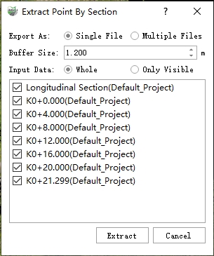
Parameter Dialog
Parameter Description
- Export As:
- Single File: The sliced point cloud will be stored as one LiData file.
- Multiple Files: The point clouds sliced from each axis will be independently stored as separate LiData files.
- Buffer Zone: The cutting range in the horizontal direction (based on each axis).
- Input Data:
- All: Use all point clouds.
- Only Visible: Only use the currently displayed point clouds for slicing calculations.
Steps
1.Adjust parameters.
Parameter Dialog
2.Run.