Detect Damage By Point Cloud
Function Description: Detects pavement damage areas based on point cloud geometric feature analysis, identifying six damage types (rutting, undulation, cracking, potholes, shallow pits, and bumps) to provide calculation data for PCI. Compared to Detect Damage By Point Cloud, Detect Damage By Images offers higher recognition accuracy. When image data is available, Detect Damage By Images is recommended as the preferred method.
Steps
1.Click the Detect Damage By Point Cloud ![]() button to open the following dialog:
button to open the following dialog:
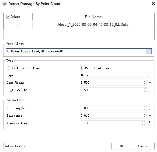
Detect Damage By Point Cloud Dialog
2.After completing the settings, click Detect to initiate damage detection.
3.Upon completion, two types of results will be generated: vector polygons and point cloud additional attributes.
Vector Polygons: Vector results are stored as polygons in the "Damage Areas" layer, recording information such as damage type, severity level, area, length, width, and maximum depth for each damage area.
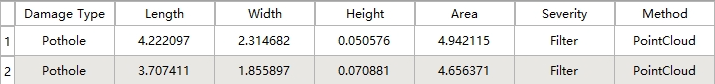
Damage Polygons
Point Cloud Additional Attributes: The depth value of each damaged point in the point cloud is written to the additional attribute "DamageDistance" and can be visualized as follows:
Display: In the Display Mode window, select "Intensity" from the Color dropdown, check With Pavement Damage, and configure the settings as shown below:
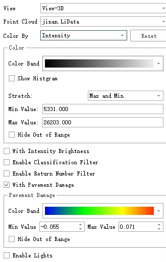
Pavement Damage Rendering Settings
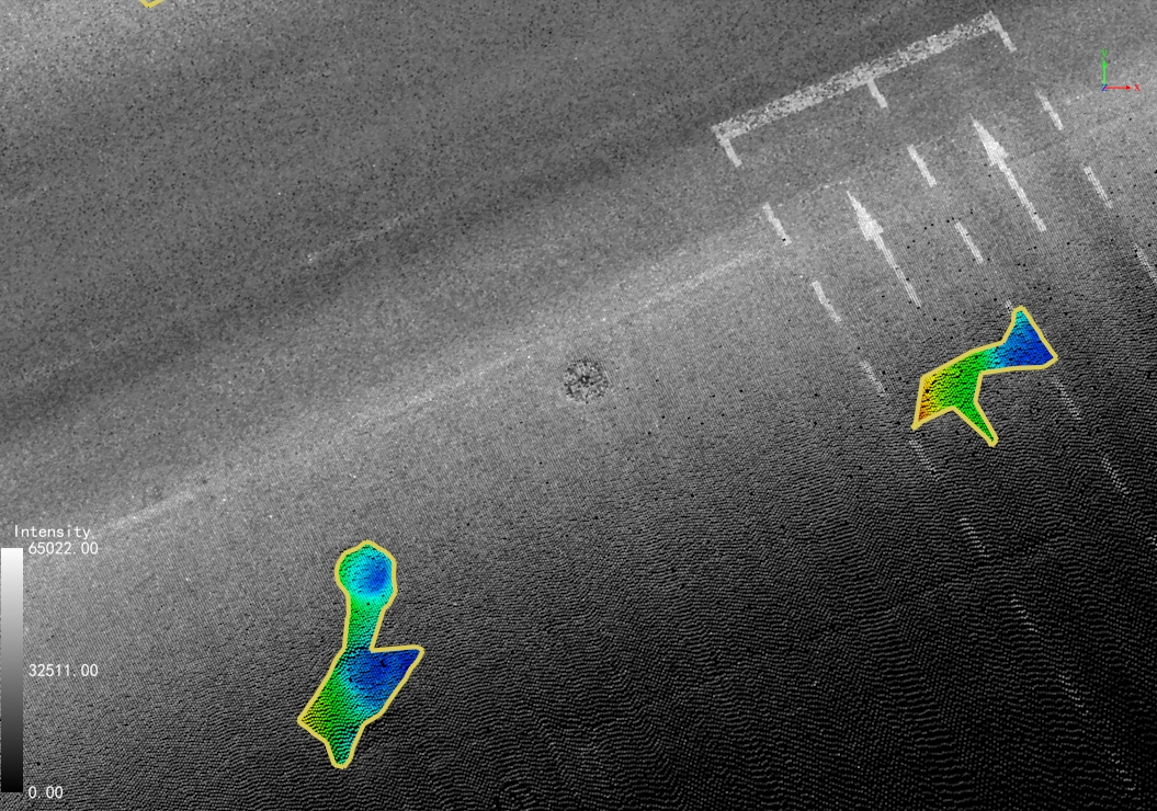
Pavement Damage Rendering
View Depth Values: Use the Single Point Selection tool to retrieve the "DamageDistance" attribute value for specific points.
Parameter Settings
Point Cloud File: Select the point cloud file to be analyzed.
Source Class: If point cloud classification has been performed, select the "Ground Points" class; otherwise, select all classes. (For more accurate results, pre-classification is recommended.)
Type: Two options are available:
Pick Point Cloud: Used for localized detection within a selected point cloud area.
Pick Road Line: Used for full-road detection. The analysis area is divided into standard blocks (225 m² each) along the road centerline based on the specified left/right widths.
Layer: Lists all line layers in the current project. Selecting a layer will use all its vector objects as road lines.
Left Width: Defines the left-side detection range relative to the road centerline.
Right Width: Defines the right-side detection range relative to the road centerline.
Parameters
Fit Length: The length of the damage detection strip, typically matching a lane width. Increase this value for larger damage areas.
Tolerance: The damage threshold. Areas with depths below this value will be filtered out.
Minimum Area: The area threshold. Damage regions smaller than this value will be filtered out.