Why are there Many Black Holes in My Colored Point Cloud?
A few weeks ago, GVI Technical Support Team was asked such a question. The screenshot related to question was shown as follows. In this screenshot, it is very clear that some parts of the data are missing. However, if users select to display the point cloud data by height, they will find that the points are not missing in the black area. So, what’s happening here?
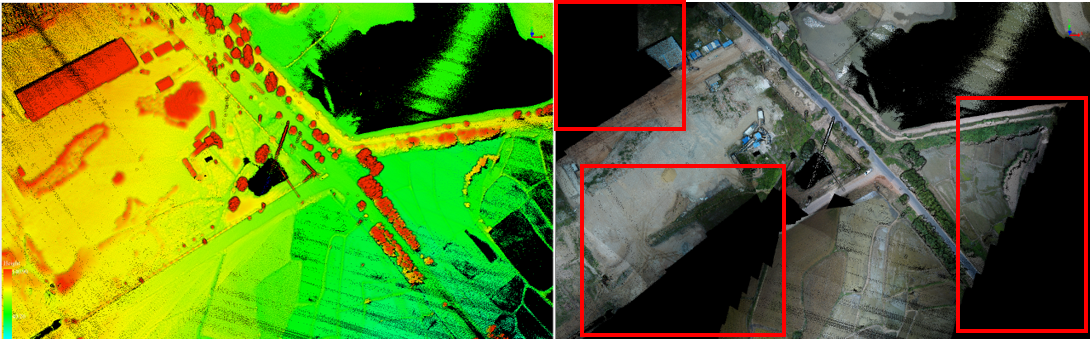
First of all, if the points are not missing while the colored points are black, it means that the black points are not covered by any photos. But why is that the ground objects can be scanned by laser scanner while they cannot be scanned by camera? The answer is that the field of view (FOV) of the LiDAR system is larger than that of the camera.
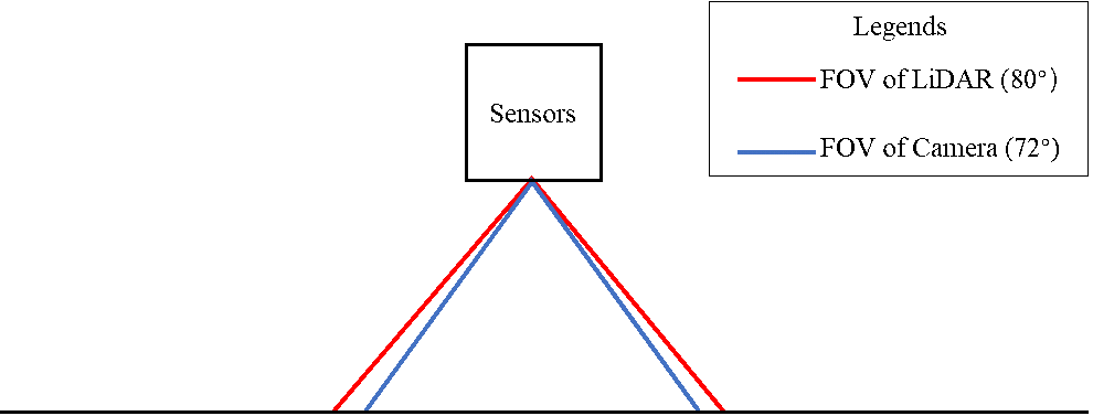
Note: The field of view of LiDAR scanner is 360°. But if we take the accuracy and ranging distance into consideration, the recommended FOV of LiDAR scanner to use for data collection for LiAir is 80° directly below the sensor, as shown in the figure 2.
Thus, the area covered by LiDAR scanning will be larger than the area covered by camera scanning. If the distance between two paralleled routes are too large, there might be no or not enough side overlap between camera data to ensure photo coverage.
Back to the data with black holes, the points without color are not captured by any photos, because distance between flight routes are too large.
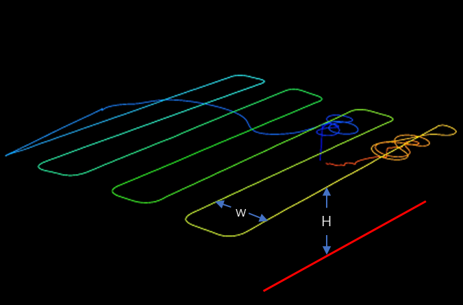
So, what is the recommended distance between each two routes? The answer is: it depends on the flight height above ground. In the flight route shown in the following figure, the distances between each two paralleled routes are marked as W, and the height above ground surface or forest canopy the red line in the picture, is marked as H. GVI recommends that the ratio of H to W (H : W) is at least 3 : 4 if your LiAir system has a camera module. This ratio will ensure enough side overlap of photos. Further, the normal flight speed of the UAV (usually 5 to 10 m/s) will ensure enough front overlap.
Note: H is the height above the surface under the aircraft instead of the takeoff point. Therefore, if you are flying over a fluctuate landscape or forest canopy, please make sure you maintain the 3:4 ratio at the higher point of the landscape.
Users can follow these steps to plan their flight route:
- Plan your above-ground flight height based on your LiAir model. Different models of LiAir have different typical operation height. For LiAir 50 series, the typical operation height is about 50 meters; for LiAir 200/220 series, the typical operation height is 80~120 meters; while for LiAir 250, the typical operation height is about 80~150 meters. Note: this height is the height above the scanning objects (e.g. ground surface, mountain slope, canopy level of trees)
Based on the planned flight height, calculate the distance between each two paralleled flight routes.
Generate flight route over the area to be surveyed.
The upcoming version of LiPlan provides capability of generating flight route automatically with correct overlapping ratio of photos entered by users. Further, the built-in global digital elevation model service is used to generate terrain-following flight route, of which the height above ground remains unchanged. Please visit our website for more detail.